Gimbal system with linear mount

a technology of gimbal and linear mount, which is applied in the field of gimbal systems, can solve the problems of affecting the field of view of the camera, affecting the image quality of the camera,

Active Publication Date: 2012-12-13
TELEDYNE FLIR LLC
View PDF9 Cites 77 Cited by
  • Summary
  • Abstract
  • Description
  • Claims
  • Application Information

AI Technical Summary

Problems solved by technology

Aircraft vibration can degrade camera performance.
Images from the camera can be unsteady and/or blurred if the field of view of the camera is not stabilized during flight.
In particular, small, vibration-induced changes to the angular orientation of the camera, relative to the aircraft, can produce unacceptably large shifts in the field of view, even if the camera is being used to view a distant scene.
However, such active compensation may need to be applied with great accuracy, hig

Method used


Image

  • Gimbal system with linear mount
  • Gimbal system with linear mount
  • Gimbal system with linear mount

Examples


example 1

Exemplary Imaging Unit with a Gear-Coupled Linear Mount

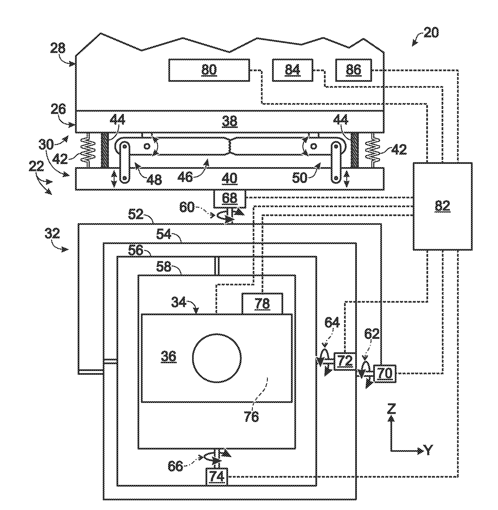
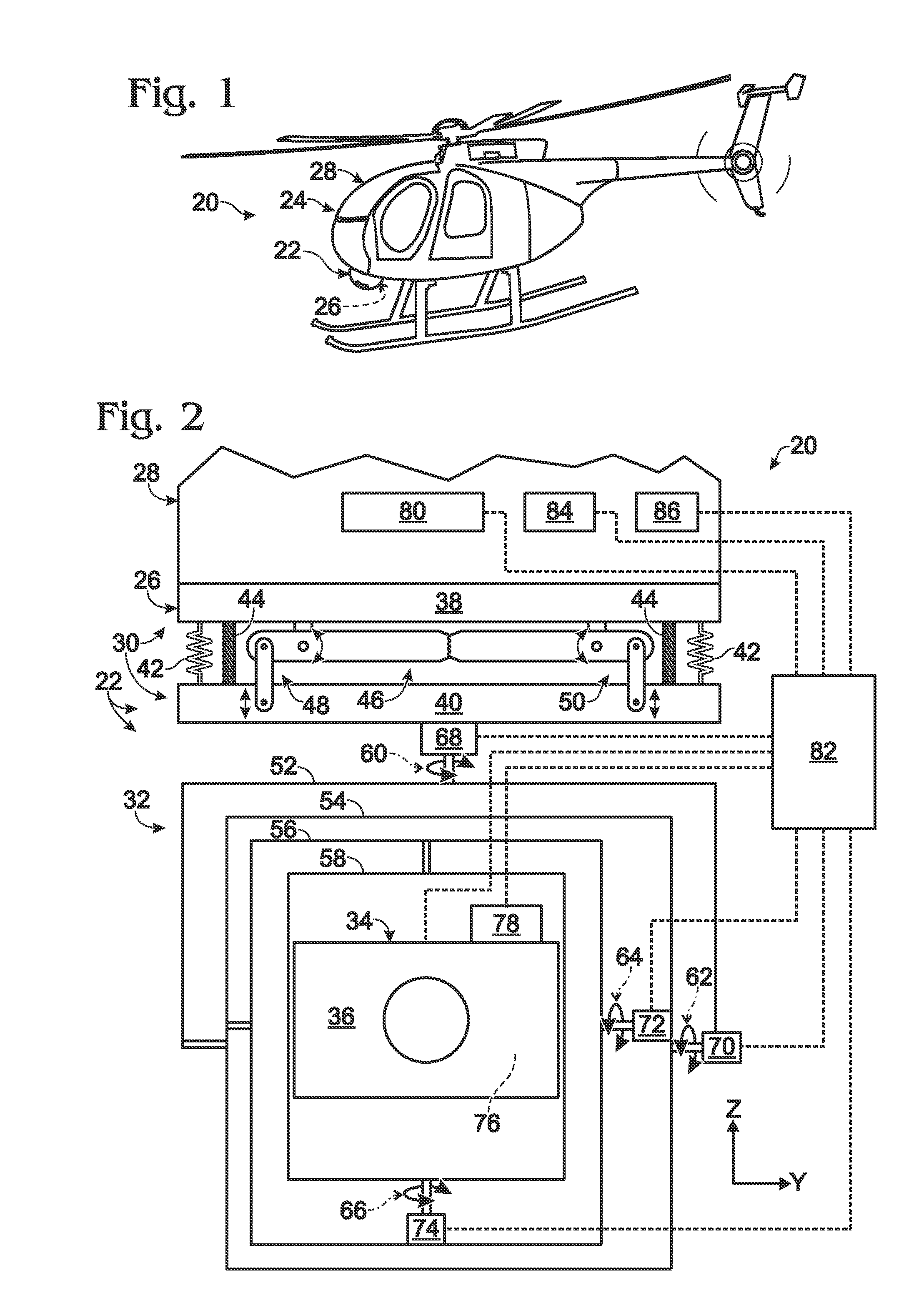
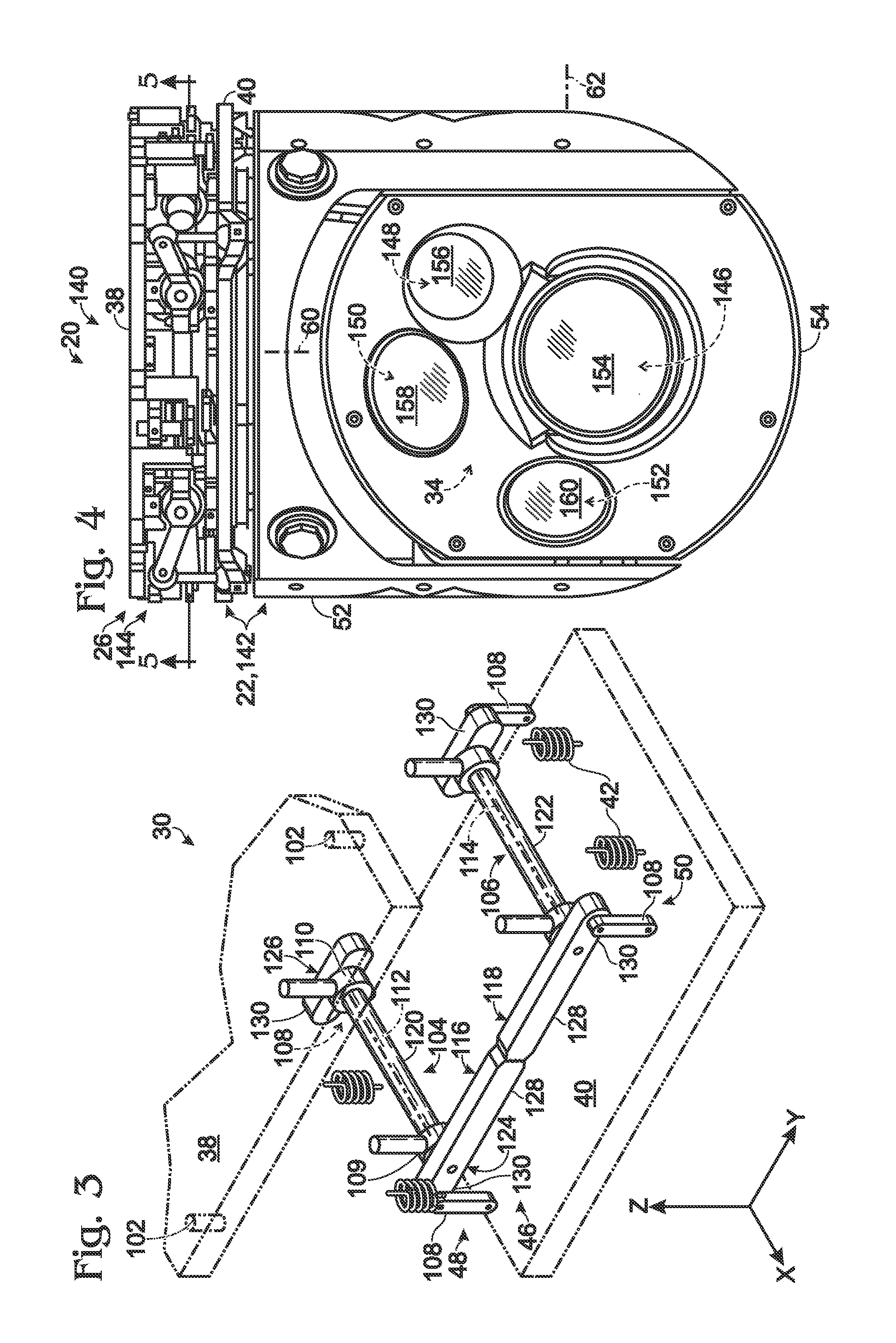
[0063]This example describes an exemplary imaging unit 140 that may form at least part of gimbal system 20 and including an exemplary embodiment 142 of gimbal apparatus 22 attached to an exemplary embodiment 144 of linear mount 26; see FIGS. 4-7. Other structural elements and features of unit 140 described previously with respect to FIGS. 2 and 3 generally have been assigned the same reference numbers as in FIGS. 2 and 3.

[0064]Second gimbal 54 supports and encloses payload 34. The payload may include a plurality of optical devices, such as an infrared camera 146, a video camera for visible light (e.g., a closed-circuit television camera) 148, a laser rangefinder 150, a light source that serves as a pointer and / or illuminator 152, or any combination thereof. The second gimbal also may be equipped with one or more optical windows 154-160 that allow optical radiation to enter or exit the second gimbal, such that the optical radiati...

example 2

Alternative Linkage for a Gear-Coupled Linear Mount

[0073]This example describes an alternative linkage for a linear mount 244; see FIG. 8.

[0074]Mount 244 may be structured and may operate generally as described for linear mount 144 (e.g., see FIGS. 5-7). However, bar assemblies 104, 106 of mount 244 incorporate shorter transverse members 168. The transverse members form gears 116, 118 and a pair of longer arms 128, but not shorter arms 130 for attachment of linkage members 108 (e.g., see FIGS. 5 and 6). Instead, arms 128 form respective attachment sites 172 for linkage members 108. Each site 172 is disposed intermediate the rotation axis and teeth 170 of the corresponding arm 128.

example 3

Selected Embodiments

[0075]This example describes selected embodiments of the present disclosure as a series of numbered paragraphs.

[0076]1. A gimbal system, comprising: (A) a gimbal apparatus including a first frame and a plurality of gimbals supporting a payload that is orientable with respect to the first frame about a plurality of axes by motor-driven rotation of the gimbals; and (B) a mount assembly including a second frame, first and second bar assemblies pivotably connected to the second frame for rotation about a pair of spaced axes and rotationally coupled to each other by a pair of gears, and a plurality of linkage members connecting the bar assemblies to the first frame, such that coupled rotation of the first and second bar assemblies produces motion of the gimbal apparatus along an axis.

[0077]2. The gimbal system of paragraph 1, wherein the second frame defines a plane, and wherein the motion of the gimbal apparatus is at least substantially orthogonal to the plane.

[0078...


PUM


Abstract

Gimbal system, including method and apparatus, for mounting a gimbal apparatus to a support platform with a mount assembly. The mount assembly may include first and second bar assemblies that are rotationally coupled to each other by a pair of gears.

Description

INTRODUCTION[0001]An aircraft may be equipped with a gimbal system including a camera. The gimbal system enables the camera to be accurately pointed as the attitude and location of the aircraft changes during flight. Accordingly, the camera can be panned and tilted to survey a wide field of view or to monitor a specific target from the flying aircraft. The camera may provide a line of sight not available to the pilot and / or may detect optical radiation, such as infrared radiation, that is invisible to the human eye.[0002]Aircraft vibration can degrade camera performance. Images from the camera can be unsteady and / or blurred if the field of view of the camera is not stabilized during flight. In particular, small, vibration-induced changes to the angular orientation of the camera, relative to the aircraft, can produce unacceptably large shifts in the field of view, even if the camera is being used to view a distant scene.[0003]The gimbal system may stabilize the camera through servome...

Claims


Application Information

Patent Timeline
IPC IPC(8): F16M13/00G05B15/02F16F3/00
CPCF16F3/00G05B15/02B64D47/08F16M11/126G03B17/561F16M11/2014G08B13/1963H04N5/23258G03B15/006F16M11/18B64U20/87H04N23/6812
Inventor PETTERSSON, DANIEL
Owner TELEDYNE FLIR LLC
Why Eureka
Try Eureka