Burner system for waste plastic fuel

a burner and plastic fuel technology, applied in the direction of solid fuel combustion, combustion types, lighting and heating apparatuses, etc., can solve the problems of long burners and significant heat loss, and achieve the effects of reducing burner size, improving heat efficiency, and improving oxidation

Inactive Publication Date: 2012-12-20
BANG WILLIAM HUNKYUN +1
View PDF5 Cites 17 Cited by
  • Summary
  • Abstract
  • Description
  • Claims
  • Application Information

AI Technical Summary

Benefits of technology

[0006]The present invention relates generally to burners that use solid fuels, especially waste plastic fuels. Burner size is minimized by having multiple combustion chambers arranged concentrically around a rotating screw conveyor. Heat efficiency is improved by having an air chamber disposed around the combustion chambers, because the air for the combustion is preheated prior to being delivered to the combustion chambers, while the air chamber at the same time thermally insulates the combustion chambers against the environment. Waste plastic is transported from a fuel hopper to the combustion chambers by a rotating screw conveyor having spiraling auger blades. Speed of the screw conveyor rotation controls the consumption of waste plastic and, hence, the amount of thermal energy generated in the burner. Parts of the combustion chambers can also rotate to auger waste plastic for better oxidation, therefore enhancing the combustion process.
[0007]In one embodiment, a burner system for waste fuel, comprises 1) a combustion unit having a plurality of combustion chambers arranged concentrically around a single rotatable feed mechanism, wherein the individual ones of said combustion chambers are in fluid communication with one another; 2) an air chamber surrounding the plurality of combustion chambers facilitates preheating combustion air delivered to the plurality of combustion chambers and further facilitates insulting said plurality of combustion chambers against thermal losses to the environment; and 3) a discharge chamber in fluid communication with the plurality of combustion chambers and a boiler for heating water and / or oil to facilitate an energy conversion process.
[0023]In one aspect of the present invention, the fuel hopper comprises a rotator configured to rotate substantially inside a rotator housing, the rotator further comprising a plurality of rotator protrusions inclined opposite from the direction of the rotator's rotation, thus reducing the incidence of waste fuel sticking to a rotator housing as waste fuel approaches the feed mechanism.
[0041]In another aspect of present invention, the control system includes sensors for helping to control the operation of a variable frequency drive motor coupled to an auger rotatably feeding a waste fuel into said combustion unit, the auger being rotated at a non-operational speed, so that the waste fuel is delivered at a lean rate; and for facilitating the operation of the variable frequency drive motor for feeding the waste fuel into said combustion unit at an operational speed, so that the waste fuel is delivered at a run rate.

Problems solved by technology

Some existing waste fuel burners have multiple combustion chambers, which improve the completeness of the burning, but the combustion chambers are arranged one after another, therefore resulting in a long burner and significant heat losses due to the exposed outer surfaces.

Method used


Image

  • Burner system for waste plastic fuel
  • Burner system for waste plastic fuel
  • Burner system for waste plastic fuel

Examples


second embodiment

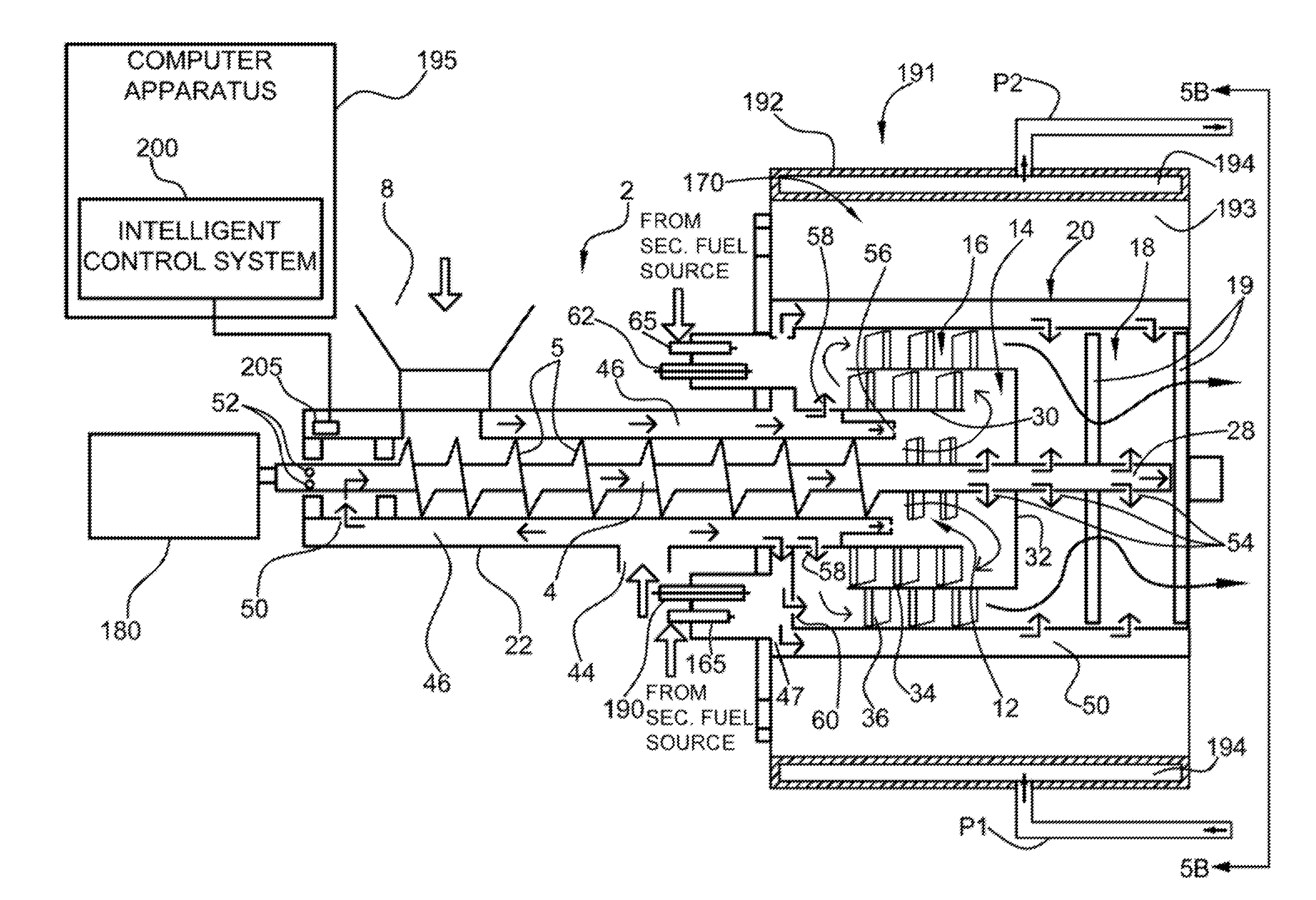
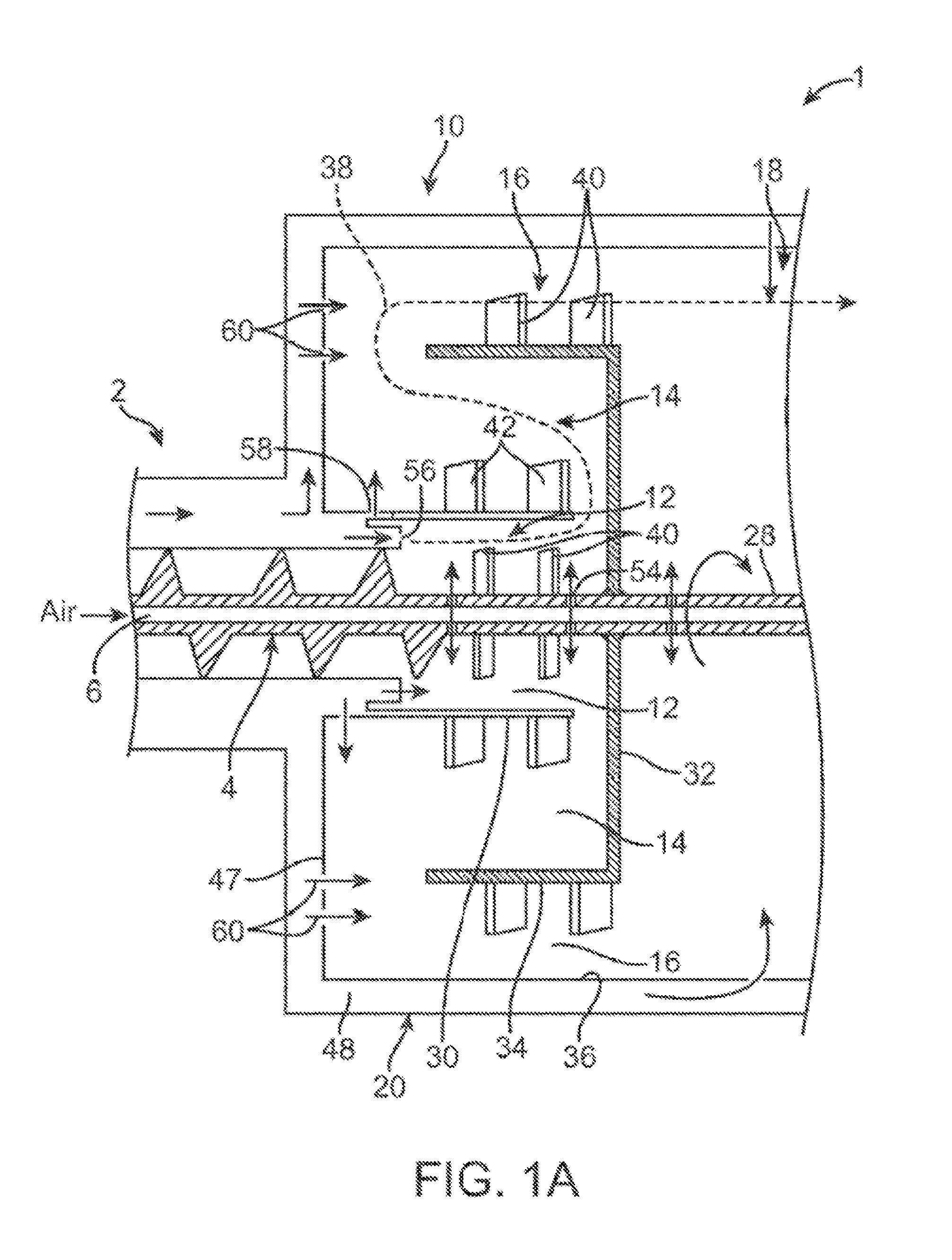
[0061]Referring now to FIG. 2, air for incinerating waste plastics is supplied from a suitable source (or sources) at an air inlet 44, like, for example, a fan or a blower (not shown) used to enhance the air intake. Air next enters inner air passage 46 defined by tubular double-walled housing portion 22. Some of the air in passage 46 is released into the space for conveyor screw 4 from an orifice 50, enters shaft lumen 6 via inlets 52, and continues to flow in the direction of combustion unit 10, while simultaneously cooling the conveyor screw 4, thus increasing the reliability of the conveyor screw 4 and its bearings. The remainder of the air in the annular inner air passage 46 continues in a downstream direction and partially encircles first combustion chamber 12. A radial air passage 47 fluidically connects axially extending inner air passage 46 with axially extending outer air passage 48, which surrounds combustion unit 10 and discharge section 18 of the burner.

[0062]As shown i...

third embodiment

[0065]Referring to FIGS. 4 and 5, there is shown an alternative or third embodiment of another burner system, generally referred to as 160. The burner system 160 includes another embodiment of a combustion unit, generally referred to as 170. In this embodiment of combustion unit 170, nose cone 30 is eliminated. Elimination of nose cone 30 increases air flow within and exiting combustion unit 170. The increased air flow and exhaust allows combustion of substantially all solid fuels moved into combustion unit 170 by conveyor screw 4. This ability to obtain substantially complete combustion of solid fuels substantially increases energy output of burner system 160 while reducing energy consumption and therefore improving overall financial performance of burner system 160 by about 50%.

[0066]Referring again to FIGS. 4 and 5, a variable frequency drive (hereinafter, VFD) motor, such as variable speed, direct drive motor 180 is coupled to conveyor screw 4 for revolving or rotating conveyor ...


PUM


Abstract

The present invention provides a burner system which uses waste fuels, especially waste plastic fuels. Burner size is minimized by having multiple combustion chambers concentrically located around a rotating screw conveyor. Heat efficiency is improved by having air passages disposed around the combustion chambers, thus preheating air for the combustion prior to its delivery to the combustion chambers, while simultaneously thermally insulating the combustion chambers against the environment. Waste fuel is transported from a fuel hopper to the combustion chambers by a rotating screw conveyor having the spiraling auger blades. Speed of screw conveyor rotation controls the consumption of waste fuel and, thus, the amount of thermal energy generated in the burner. The burner system includes an intelligent control system for controlling operation of the burner system, so that the burner system performs at optimum efficiency, safely and with minimum operator intervention.

Description

CROSS-REFERENCE TO RELATED APPLICATION[0001]This application is a continuation-in-part of application Ser. No. 12 / 367,462, filed Feb. 6, 2009, now U.S. Pat. No. ______.BACKGROUND OF THE INVENTION[0002]The present invention relates generally to fuel burners, especially burners for waste fuel, such as waste plastic. Considerable research effort has been invested toward finding methods of converting waste plastics to usable fuels as a means of plastic recycling. Waste plastics are burned to generate heat, which may be used for water heating, industrial heat, or other purposes. Important considerations related to waste plastics as fuel sources are: maximizing energy by burning the solid fuel completely, minimizing heat losses to the environment, compactness of the burner, and minimizing soot and harmful gases emission.[0003]Some existing waste fuel burners have multiple combustion chambers, which improve the completeness of the burning, but the combustion chambers are arranged one after...

Claims


Application Information

Patent Timeline
Patent Type & Authority Applications(United States)
IPC IPC(8): F23G7/12F23L15/00F23G5/38
CPCF23G5/16F23G2900/508F23G5/50F23G7/12F23G2205/121F23G2207/20F23M9/003F23M9/06Y02E20/12F23G2206/203F23K2203/202F23G5/38F23G5/46F23L15/00F23G2209/28F23G5/12F23G5/444Y02E20/34F23N1/002F23N5/02F23N5/20F23N2225/04F23N2225/08F23N2229/00
Inventor BANG, WILLIAM HUNKYUNPATERNOSTRO, THOMAS ANTHONY PATTI
Owner BANG WILLIAM HUNKYUN
Why Eureka
Try Eureka