Low voltage detector

a low-voltage detector and circuit technology, applied in the direction of thermoelectric instruments, electric devices, instruments, etc., can solve the problems of low-power reliability, disadvantageous occupied area of known low-voltage detectors, and low-power consumption of low-voltage detectors

Active Publication Date: 2012-12-20
NXP USA INC
View PDF6 Cites 21 Cited by
  • Summary
  • Abstract
  • Description
  • Claims
  • Application Information

AI Technical Summary

Problems solved by technology

Usually, a reliable low-power, low voltage detector consumes hundreds of microamperes because it requires one or more voltage dividers and a bandgap reference voltage to operate properly.
The ladder resistors are usually large so that known low voltage detectors consume low power.
Such large ladder resistors may cause known low voltage detectors to occupy a disadvantageously large area.
When a low voltage detector uses a reference voltage that depends upon the threshold voltage, a part-to-part variation of the low voltage detector is disadvantageously great.
Therefore, such a low voltage detector is either disadvantageously affected by temperature changes, or it requires additional circuitry that provides temperature compensation but which consumes additional power.
Moreover, such a low voltage detector may need trimming to counterbalance the part-to-part variation.

Method used


Image

  • Low voltage detector
  • Low voltage detector
  • Low voltage detector

Examples


Embodiment Construction

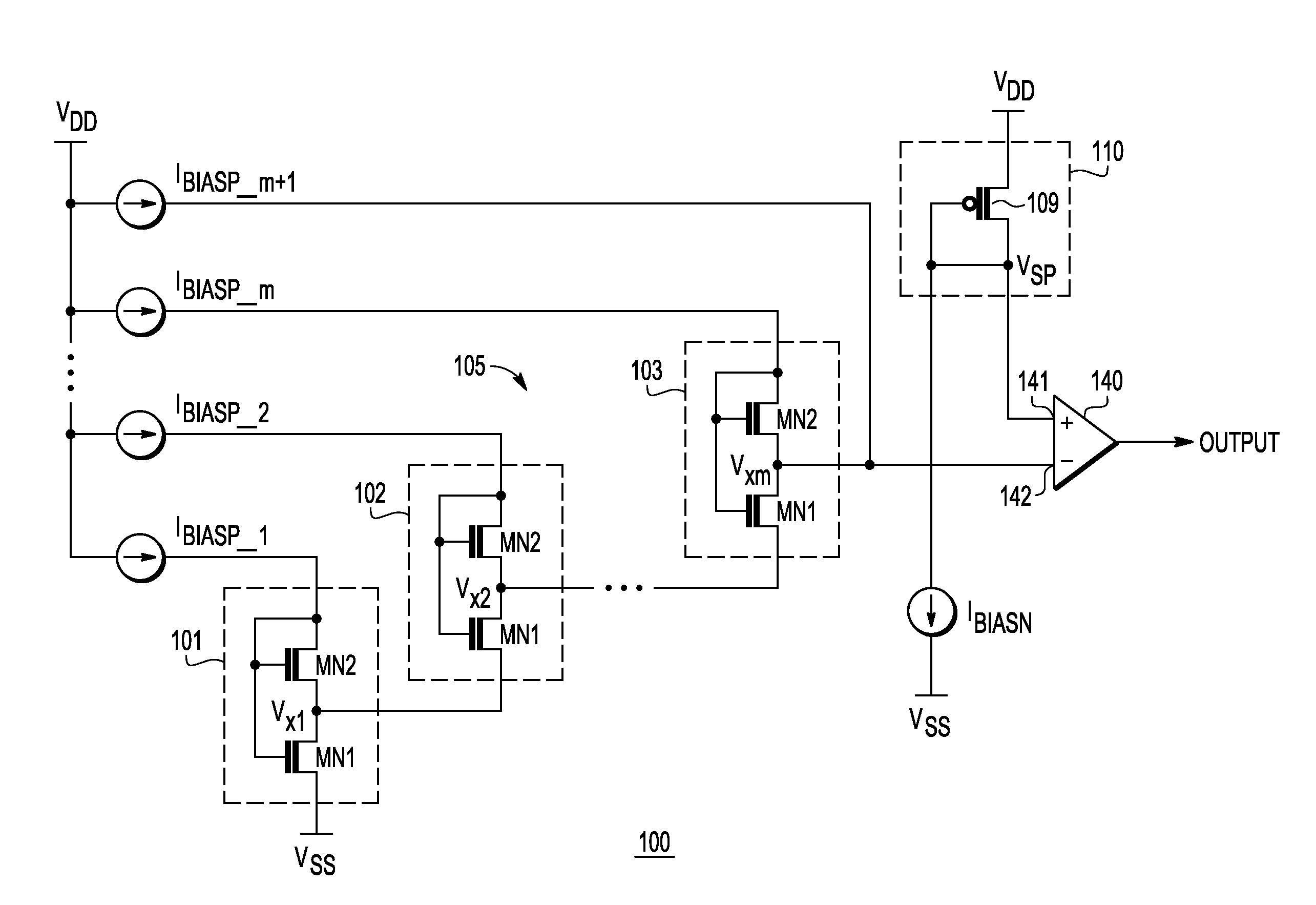
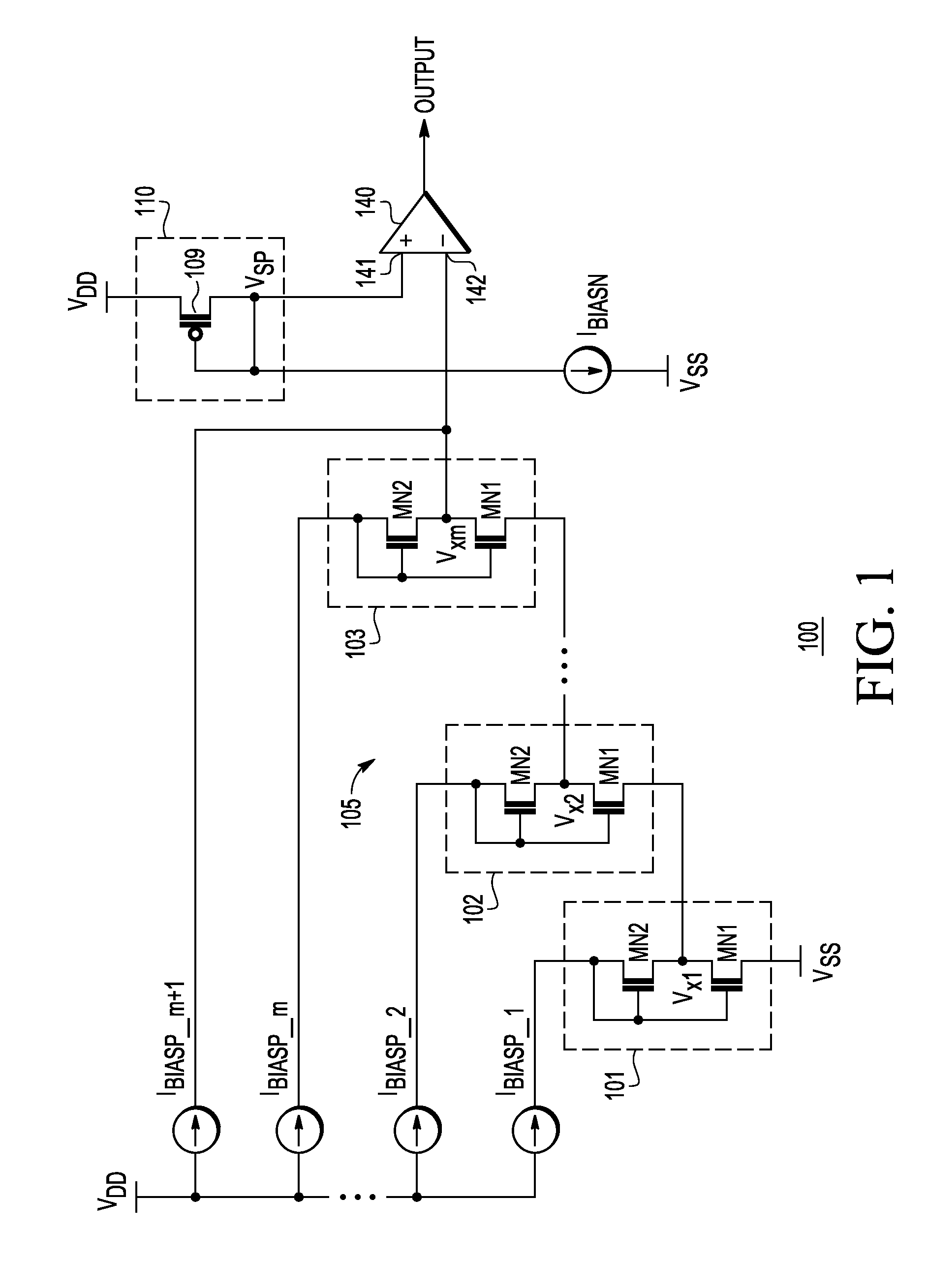
[0019]FIG. 1 is a schematic of a low-power, low voltage detector (LVD) 100 in accordance with the invention, which, in some embodiments, achieves reliable low voltage detection while consuming power in a nanowatt range. The LVD 100 advantageously self-compensates for changes in its temperature.

[0020]In one embodiment, the LVD 100 comprises a proportional to absolute temperature (PTAT) voltage generator 105, a power supply voltage monitor 110, and a voltage comparator (hereinafter “comparator”) 140. In one embodiment, the comparator 140 is a low power consumption comparator. In one embodiment, the LVD 100 is disposed on a substrate of an integrated circuit. The LVD100 may be coupled to a nanowatt-range current reference that provides bias currents, IBIASN and IBIASP—1 to IBIASP—m+1, for the LVD. Besides consuming low power, such a nanowatt-range current reference should operate down to, or below, a minimum trip point of the LVD 100. In other words, if the trip point of the LVD 100 is...


PUM


Abstract

A low voltage detector (100) includes a power supply voltage monitor circuit (110) that produces a voltage VSP related to a first a power supply voltage, and a voltage generator (105), which includes a plurality of self-cascode MOSFET (SCM) structures (101-103) in a cascade configuration, that generates a reference voltage Vxm. A voltage comparator (140) outputs an output signal in response to a differential between Vxm and VSP, wherein Vxm and VSP have proportional to absolute temperature behavior (PTAT) over temperature with respect to a second power supply voltage. The output signal changes state when the first power supply voltage equals a trip point of the comparator. Each SCM structure is sized to provide a rate of change with temperature of the PTAT behavior of Vxm that matches a rate of change with temperature of the PTAT behavior of VSP.

Description

BACKGROUND[0001]1. Field[0002]This invention relates generally to voltage detector circuits, and more specifically to a low power consumption, low voltage detector circuit.[0003]2. Related Art[0004]Electronic devices frequently employ a voltage detector to indicate if a particular voltage is outside a specified range. For example, a battery operated device often includes a voltage detector to provide a low voltage indication when the voltage supplied by a battery decreases below a predetermined level. The low voltage indication can notify a user of the device that the battery should be replaced or recharged. Usually, a reliable low-power, low voltage detector consumes hundreds of microamperes because it requires one or more voltage dividers and a bandgap reference voltage to operate properly.[0005]There are current-based, low voltage detectors, but they require nonstandard CMOS devices such as bipolar transistors and non-volatile memory (NVM) cells.[0006]Some known low voltage detec...

Claims


Application Information

Patent Timeline
Patent Type & Authority Applications(United States)
IPC IPC(8): G06F19/00G01R21/14G01R19/00
CPCG01R19/16519G01R19/16542G01R19/16576G01R19/32
Inventor VILAS BOAS, ANDRE LUISOLMOS, ALFREDOCAMACHO GALEANO, EDGAR MAURICIODE LACERDA, FABIO
Owner NXP USA INC
Why Eureka
Try Eureka