
Device and method for the continuous treatment of masses a

Inactive Publication Date: 2012-12-27
KNOBEL AXEL
View PDF0 Cites 2 Cited by
  • Summary
  • Abstract
  • Description
  • Claims
  • Application Information

AI Technical Summary

Benefits of technology

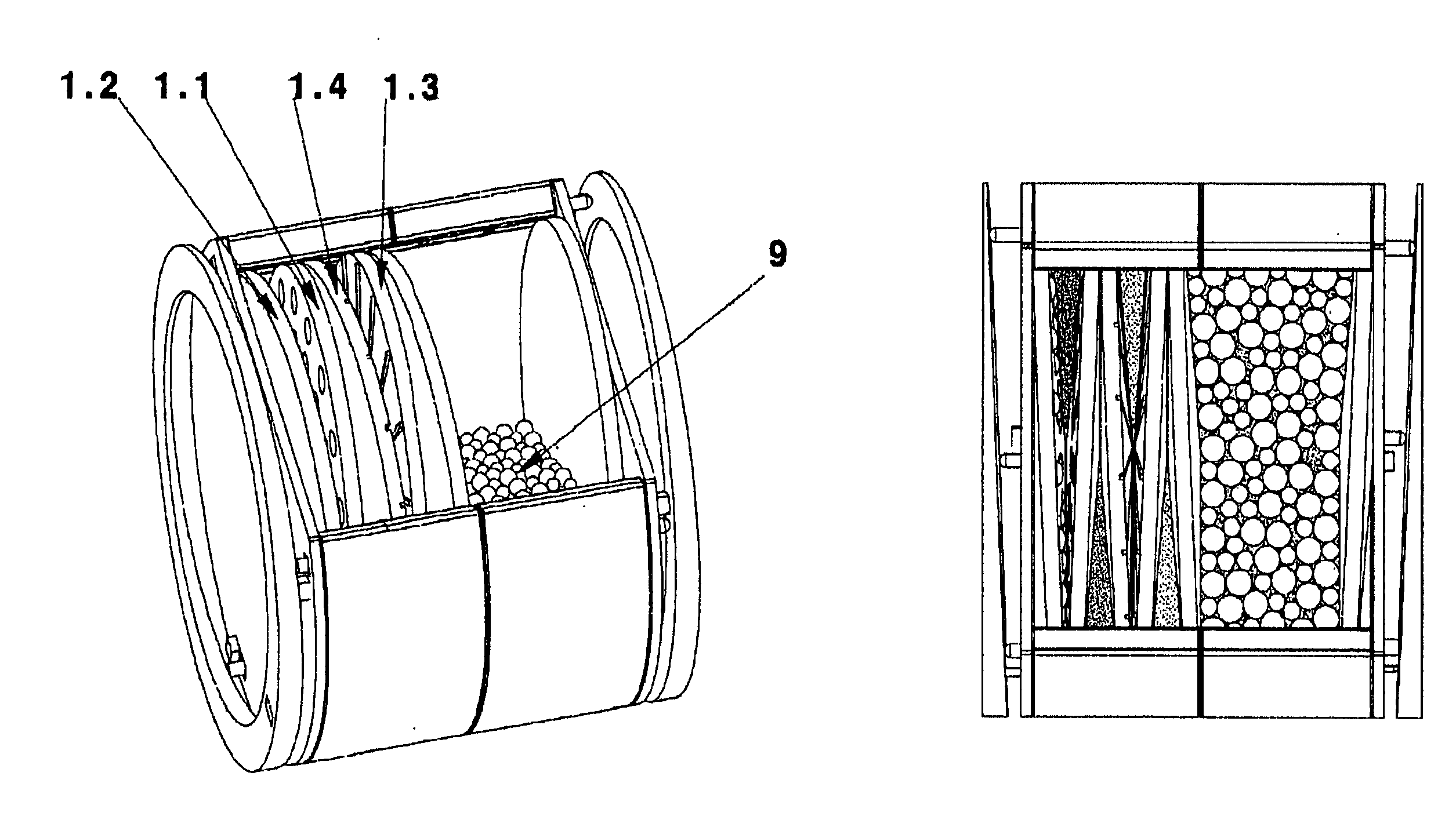
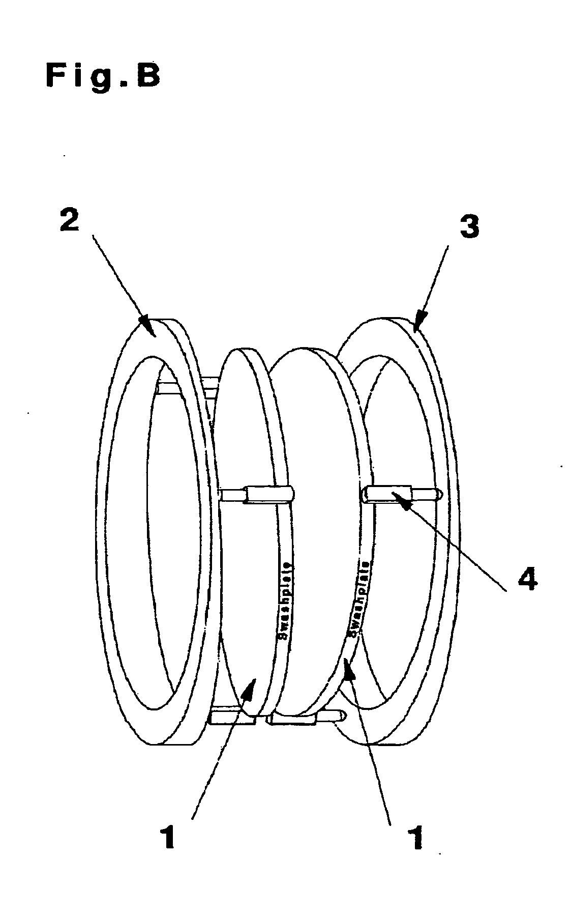
[0011]In a first arrangement the swashplates are arranged so that the lateral surface[s] on the line from the apex to the outside diameter lie on one another, unroll with respect to one another without rotating radially about their own axis. The swashplates are made to tumble by means of cam disks which are connected to the swashplates by means of tumble thrust shafts and are also controlled. The cam disks can be designed to be both mechanically and also servo controlled. The swashplates are placed in a housing so that they are enclosed at the circumference. A cavity is thus formed between the swashplates. This cavity moves around the axial center points of the swashplates. The mass located therein is accordingly always guided around this fictitious axis between the axial center points. If this fictitious axis now lies horizontally and a part of the mass is located in the cavity between the swashplates and the swashplates are tumbling toward one another, the mass is pushed over this fictitious axis. If the movement is sufficiently fast, the mass swashes over. This process promotes oxygen exchange.
[0013]In a second arrangement a swashplate is placed above a horizontal fixed plate. The swashplate tumbles over the fixed plate. The term fixed plate in this connection must be understood such that it does not tumble. It can rotate about its own axis and / or change position. The swashplate is in particular servo-controlled or driven by means of a cam disk. It is thereby possible to make the swashplate tumble so that a function for a mill (milling function) is obtained together with the fixed plate. Compared with many known systems this arrangement has the advantage that more parameters are available for adjustment. Along with known adjustments such as circumferential speed of the rollers (fixed plate), friction, grinding gap and swashplate temperature (roller temperature), it is also possible to run engaging angle, gap angle as well as large and small speed differences. It is possible to make the fixed plate rotate so that, for example, the milling material remains precisely in the working area due to the centrifugal force. However, this can also be achieved by the gap angle. As a result, the milling material can remain in the mill until, for example, a desired grain size is achieved,
[0014]In a third arrangement the swashplates are as described under [009] but there is a distance between the lines on the lateral surfaces from the apex to the outside diameter. The space thereby enlarged is filled with grinding bodies or spheres as well as milling material. The grinding bodies or spheres and the milling material are now milled by the tumbling movements of the swashplates. Compared with conventional ball mills, however, use is made of the advantage that more energy can be introduced in a controlled manner with the swashplates. Furthermore, it is possible to couple modules with swashplates for subsequent process steps.

Problems solved by technology

Temperature controls can usually only be achieved via the housing wall and are accordingly difficult and sluggish.
Mills are frequently built for a specific purpose and are not universally usable.
The contact time of the milling material in roll mills between the rollers is short, which is why several milling passes are frequently required.
The grinding speed and the energy input are difficult to regulate.

Method used


Image

  • Device and method for the continuous treatment of masses a
  • Device and method for the continuous treatment of masses a
  • Device and method for the continuous treatment of masses a

Examples


Embodiment Construction

[0006]The invention is based on the object of increasing the energy input (mechanical and / or thermal) and the substance input (e.g. gassing) and also the substance removal (e.g. degassing) in a device and a method for processing milling material and masses in order to reach the final state of the milling material or the mass desired by the processing more rapidly than with the conventional prior-art means.

[0007]In order to solve this object, the invention provides a device for processing masses, in particular chocolate masses, in which at least one swashplate (1) provided with an obtuse-angled cone on its front side, is disposed so that the apex of the swashplate (1) lies on the axis of the swashplate and the lateral surface of the swashplate (1) can extend as far as its outside diameter, wherein the swashplate (1) is shaped and disposed with respect to a mating surface opposite its obtuse-angled cone such that a line of the swashplate (1) running from the apex over the lateral surf...


PUM


Abstract

The invention relates to a device and a method for processing milling material and masses in continuous processes, in particular the treatment of fat-containing masses. Milling with one swashplate (1) with a fixed plate or two swash plates (1), conching with swashplates (1) and also, as a final process step, tempering and crystallizing by means of swashplates (1).

Description

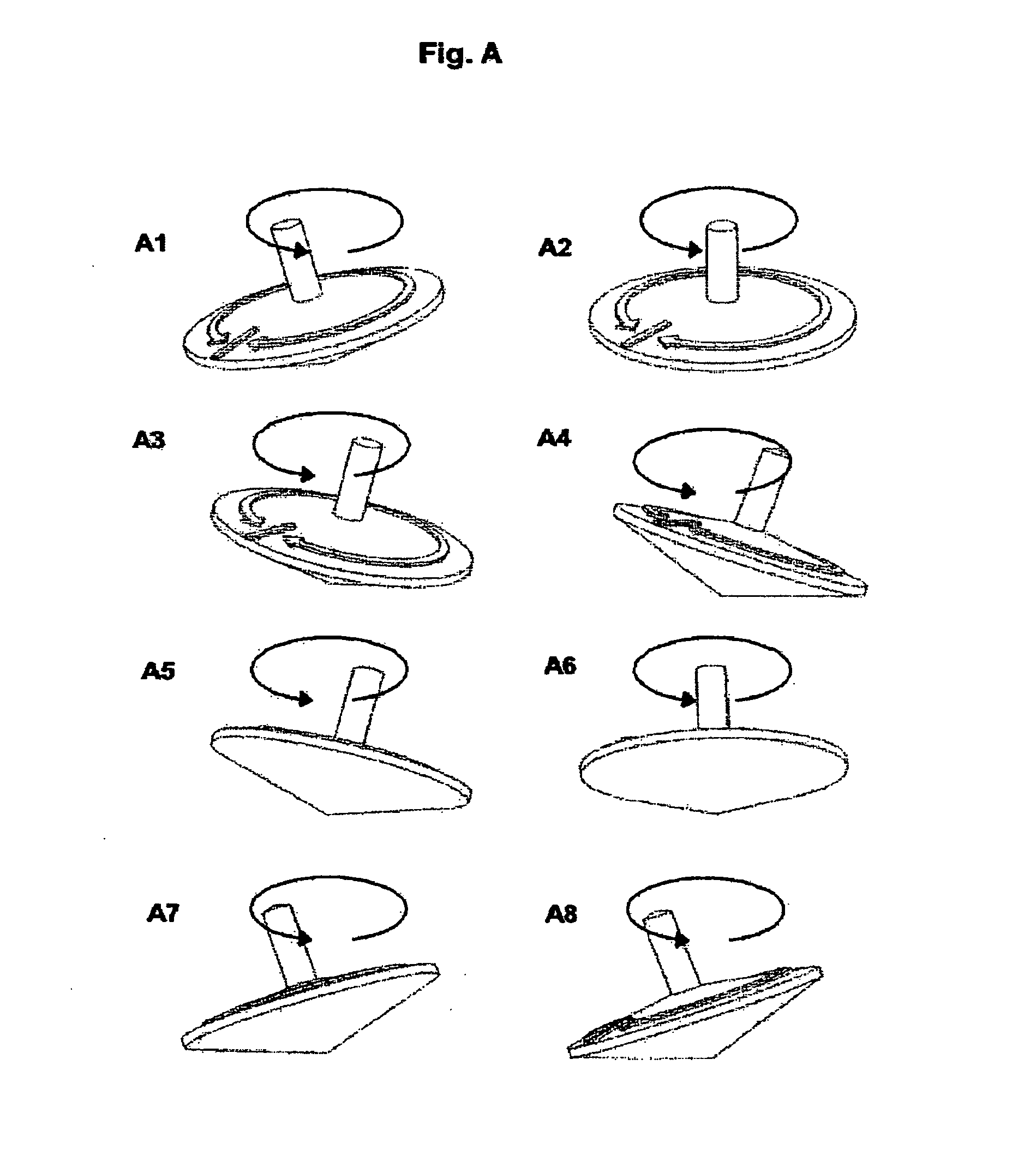
[0001]The invention relates to a principle for devices and methods which are used for the processing of masses, in particular chocolate masses. At least one swashplate is used for this principle. The mode of operation of the swashplate is generally known for use in helicopters in order to control rotor inclinations, on the other hand the swashplate is also used in hydraulic pumps.[0002]Tumbling or precession is generally the change in direction of the axis of a body when external forces exert a torque on it. The Euler equations are equations of motion for the rotation of a rigid body. In order to explain the principle of the use of the swashplate for these devices, one can envisage a top which, when it loses momentum, falls onto the plane with the lateral surface of the cone and then rolls around the apex. This rolling around the apex shows clearly the principle of the swashplate used here.PRIOR ART[0003]When mixing, comminuting and texturing masses, in particular chocolate masses, ...

Claims


Application Information

Patent Timeline
IPC IPC(8): A47J43/04
CPCA47J43/07
Inventor KNOBEL, AXEL
Owner KNOBEL AXEL
Learn More