Light emitting diode having electrode pads

Active Publication Date: 2012-12-27
SEOUL VIOSYS CO LTD
View PDF1 Cites 29 Cited by
  • Summary
  • Abstract
  • Description
  • Claims
  • Application Information

AI Technical Summary

Benefits of technology

[0022]Exemplary embodiments of the present invention provide a light emitt

Problems solved by technology

This may be referred to as current crowding, and may lead to a reduction in light emitting area, thereby deteriorating luminous efficacy of a source.
However, since the transparent electrode layer may tend to absorb light, the is thickness of the transparent electrode layer is limited, thereby providing limited current spreading.
In particular, for a large LED having an area of about 1 mm2 or more, there is a limitation on current spreading through the transparent electrode layer.
Although the use of extensions may enhance current spreading over a wide region of the LED, current crowding may still occur at portions of the LEDs where the electrode pads are formed.
Moreover, as the size of the LED increases, the likelihood of a defect being present in the light emitting diode may increase.
Defects such as threading dislocations, pin-holes, etc. provide a path through which electric current may flow rapidly, ther

Method used


Image

  • Light emitting diode having electrode pads
  • Light emitting diode having electrode pads
  • Light emitting diode having electrode pads

Examples


Embodiment Construction

[0048]The invention is described more fully hereinafter with reference to the accompanying drawings, in which exemplary embodiments of the invention are shown. This invention may, however, be embodied in many different forms and should not be construed as limited to the exemplary embodiments set forth herein. Rather, these exemplary embodiments are provided so that this disclosure is thorough and will fully convey the scope of the invention to those skilled in the art. In the drawings, the sizes and relative sizes of layers and regions may be exaggerated for clarity. Like reference numerals in the drawings denote like elements.

[0049]It will be understood that when an element such as a layer, film, region or substrate is referred to as being “on” another element, it can be directly on the other element or intervening elements may also be present. In contrast, when an element is referred to as being “directly on” another element, there are no intervening elements present.

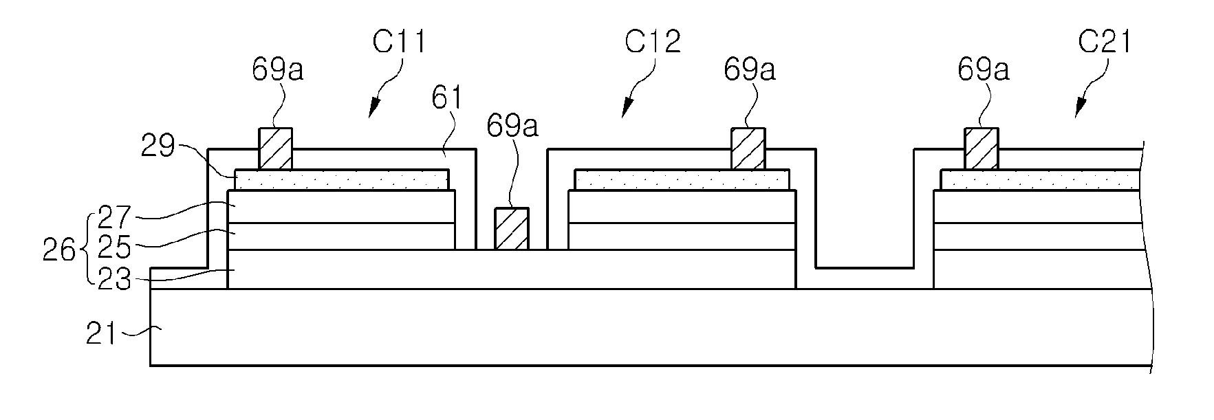
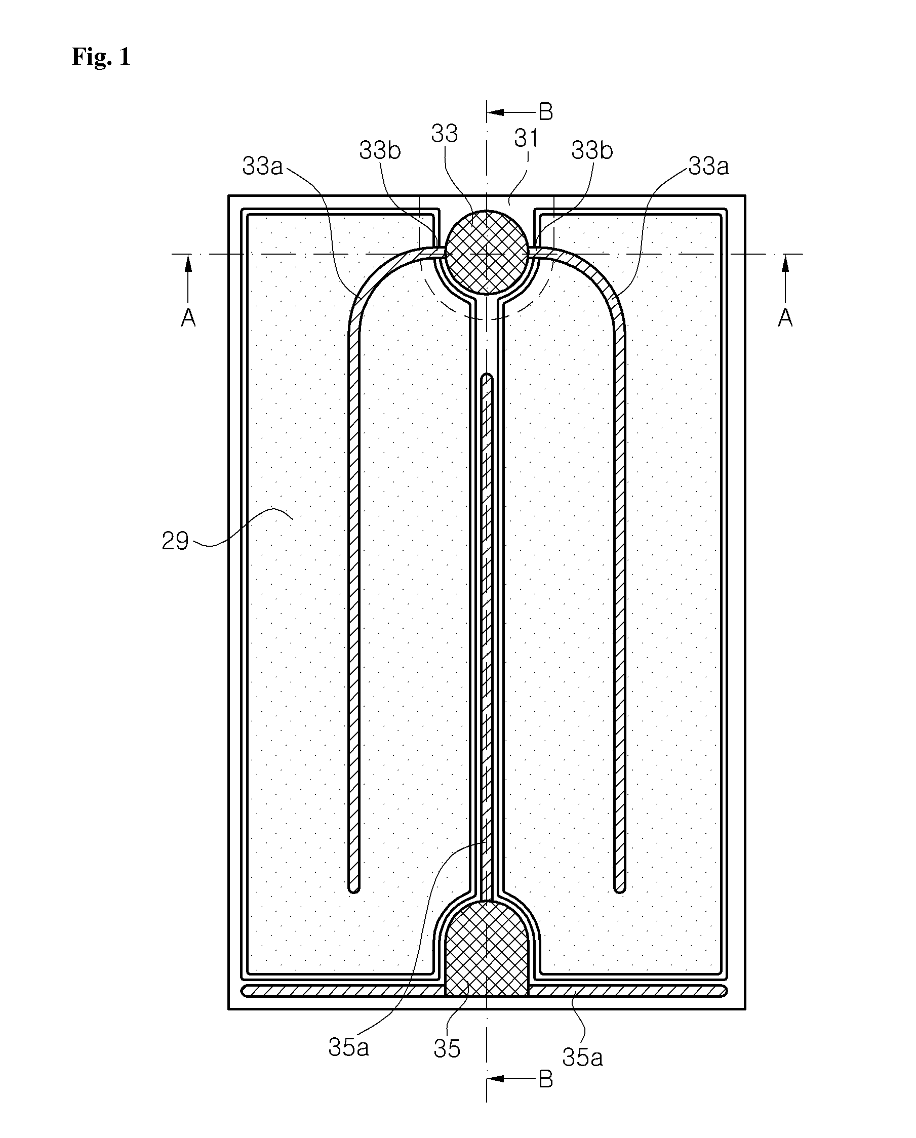
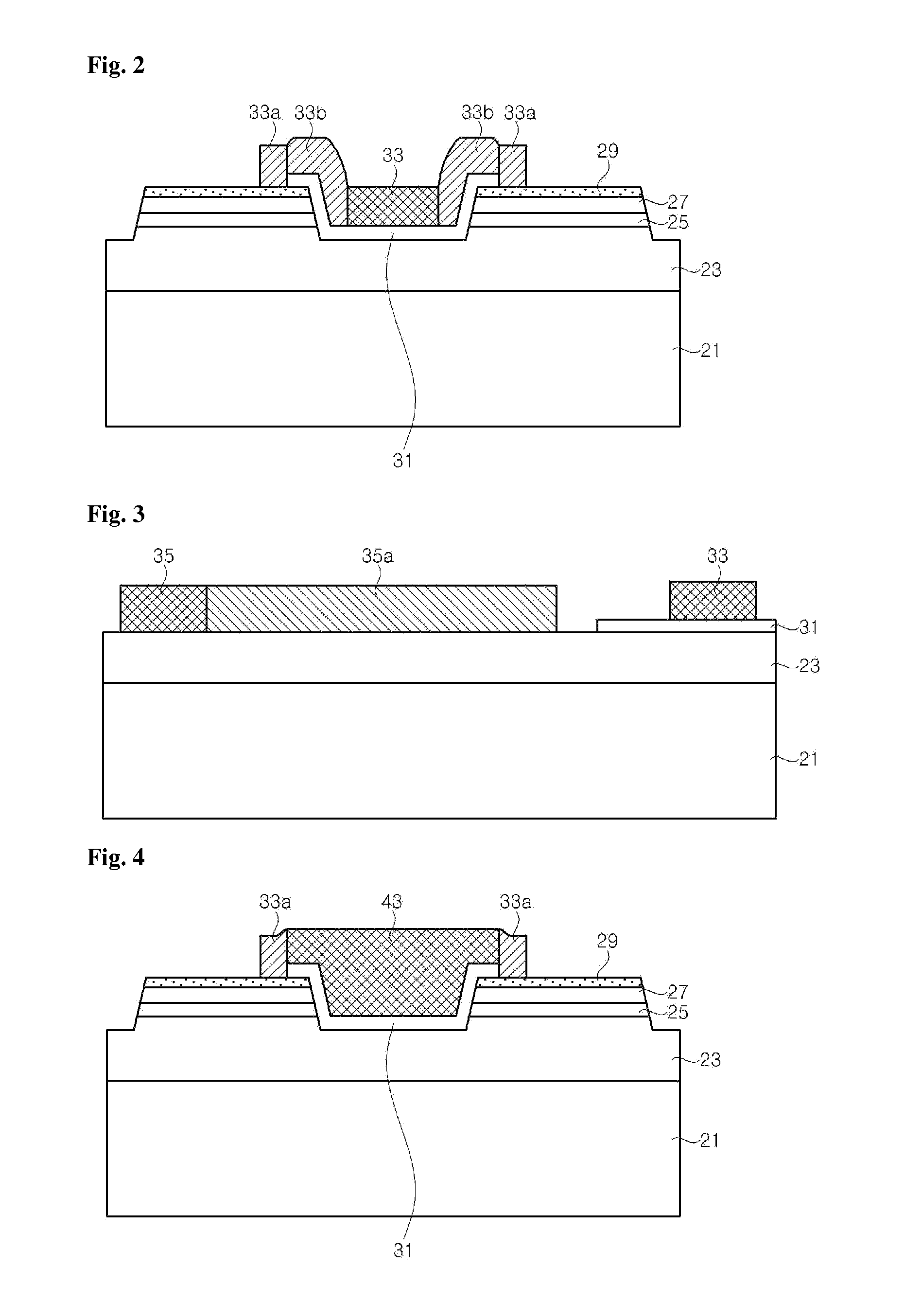
[0050]FIG. 1 ...


PUM


Abstract

The present invention relates to light-emitting diodes. A light-emitting diode according to an exemplary embodiment of the present invention includes a first group including a plurality of first light emitting cells connected in parallel to each other, and a second group including a plurality of second light emitting cells connected in parallel to each other. Each first light emitting cell and second light emitting cell has a semiconductor stack that includes a first conductivity-type semiconductor layer, a second conductivity-type semiconductor layer, and an active layer disposed between the first conductivity-type semiconductor layer and the second conductivity-type semiconductor layer. At least two light emitting cells of the first light emitting cells share the first conductivity-type semiconductor layer, and at least two light emitting cells of the second light emitting cells share the first conductivity-type semiconductor layer. The first light emitting cells are connected in series to the second light emitting cells.

Description

CROSS-REFERENCE TO RELATED APPLICATIONS[0001]This application is a continuation-in-part of U.S. patent application Ser. No. 12 / 963,921, filed on Dec. 9, 2010, and claims priority from and the benefit of Korean Patent Application No. 10-2011-0080232, filed on Aug. 11, 2011 and Korean Patent Application No. 10-2009-0123862, filed on Dec. 14, 2009, which are all hereby incorporated by reference for all purposes as if fully set forth herein.BACKGROUND OF THE INVENTION[0002]1. Field of the Invention[0003]Exemplary embodiments of the present invention relate to light-emitting diodes and to light-emitting diodes having electrode pads, and more particularly, to high voltage and / or high efficiency light-emitting diodes.[0004]2. Discussion of the Background[0005]Gallium nitride (GaN) based light emitting diodes (LEDs) have been used in a wide range of applications including full color LED displays, LED traffic signals, and white LEDs.[0006]The GaN-based light emitting diode may be generally f...

Claims


Application Information

Patent Timeline
IPC IPC(8): H01L33/62
CPCH01L33/20H01L33/38H01L33/44H01L33/387H01L2924/0002H01L33/62H01L2924/00H01L27/153H01L33/08
Inventor LEE, SUM GEUNSHIN, JIN CHEOLYOON, YEO JIN
Owner SEOUL VIOSYS CO LTD
Why Eureka
Try Eureka