
Method for extracting and separating light rare earth element

Active Publication Date: 2012-12-27
SHIN ETSU CHEM IND CO LTD
View PDF3 Cites 3 Cited by
  • Summary
  • Abstract
  • Description
  • Claims
  • Application Information

AI Technical Summary

Benefits of technology

[0015]The method enables extraction and separation of a target LREE through simple steps with the advantages of commercially acceptable efficiency, simplicity, and a small size plant. The installation investment and running cost are reduced. The method is of great industrial worth.

Problems solved by technology

A resource crisis is exclaimed because it is expected that the demand will exceed the supply in the near future.
Inversely, if the separation factor is lower, the separation process becomes more complicated and the separation system becomes of larger size.
The separation factor of this order is not sufficient to facilitate separation between neodymium and praseodymium.
To purify and separate one from the other at an acceptable purity, a large size system is necessary and capital-intensive.

Method used


Image

  • Method for extracting and separating light rare earth element
  • Method for extracting and separating light rare earth element

Examples


example

[0034]Experiments and Examples of the invention are given below by way of illustration and not by way of limitation. The concentration of an LREE in an aqueous solution was measured by an ICP atomic emission spectrometer (ICP-7500 by Shimadzu Corp.).

example 1

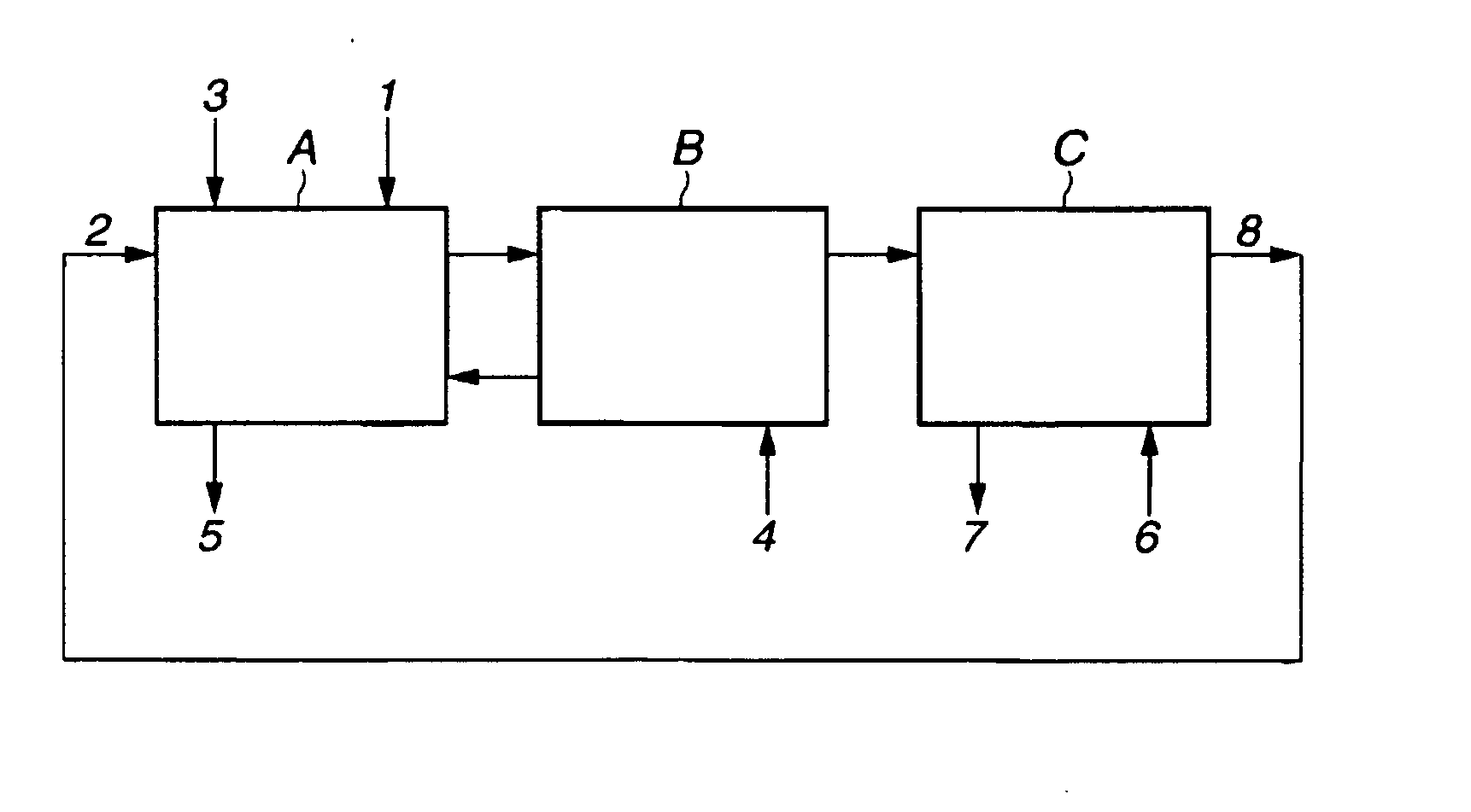
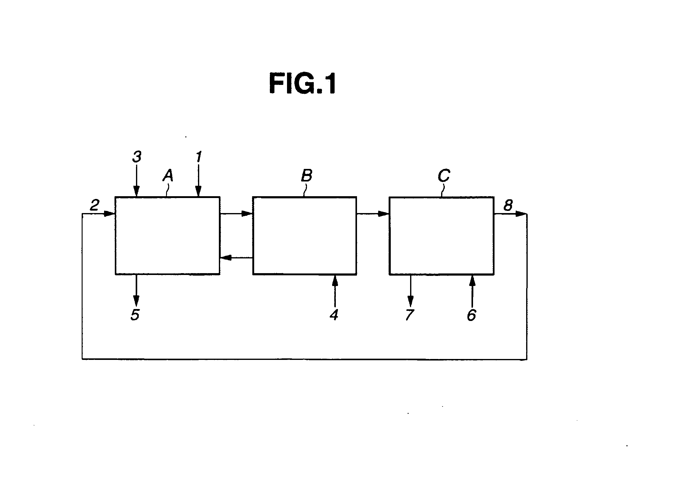
[0044]This example used a counter-current flow multistage mixer-settler including sections and flow lines as shown in FIGS. 1, and D2EHDGAA as extractant for extracting and separating neodymium, praseodymium and cerium in sequence from a mixture of lanthanum, cerium, praseodymium and neodymium.

[0045]The organic phase was a kerosine solution of 0.5 mol / L of D2EHDGAA. The aqueous phase was 30 L of an aqueous solution of lanthanum chloride, cerium chloride, praseodymium chloride and neodymium chloride in a molar ratio of lanthanum:cerium:praseodymium:neodymium=1:1:1:1 and in a concentration of 0.1 mol / L of lanthanum+cerium+praseodymium+neodymium.

[0046]A counter-current flow multistage mixer-settler as shown in FIG. 1 included an extraction section A of 14 stages, a scrubbing section B of 10 stages, and a back-extraction section C of 8 stages. The organic phase and the aqueous phase were contacted for extraction and separation at a temperature of 35° C. which was below the flash point o...

example 2

[0068]This example used a counter-current flow multistage mixer-settler including sections and flow lines as shown in FIGS. 1, and D2EHDGAA as extractant for extracting and separating neodymium from a mixture of praseodymium and neodymium.

[0069]The organic phase was a kerosine solution of 0.5 mol / L of D2EHDGAA. The aqueous phase was 30 L of an aqueous solution of praseodymium chloride and neodymium chloride in a molar ratio of praseodymium:neodymium=1:1 and in a concentration of 0.1 mol / L of praseodymium+neodymium.

[0070]A counter-current flow multistage mixer-settler as shown in FIG. 1 included an extraction section A of 12 stages, a scrubbing section B of 12 stages, and a back-extraction section C of 8 stages. The organic phase and the aqueous phase were contacted at 35° C. to effect extraction and separation. The aqueous phase was fed at a flow rate of 15 L / hr from line 1, the organic phase fed at a flow rate of 21 L / hr from line 2, a 4 mol / L sodium hydroxide aqueous solution fed ...


PUM

PropertyMeasurementUnit
Equivalent massaaaaaaaaaa

Abstract

A target light rare earth element is separated from an aqueous solution containing two or more of La, Ce, Pr and Nd by contacting an organic phase containing an extractant with the aqueous solution in a counter-current flow multistage mixer-settler while adding an alkaline solution thereto, and contacting the organic phase with an acid aqueous solution for back-extracting the target element. The extractant is a dialkyl diglycol amic acid having formula: R1R2NCOCH2OCH2COOH wherein R1 and R2 are alkyl, at least one having at least 6 carbon atoms.

Description

CROSS-REFERENCE TO RELATED APPLICATION[0001]This non-provisional application claims priority under 35 U.S.C. §119(a) on Patent Application Nos. 2011-141570 and 2012-001824 filed in Japan on Jun. 27, 2011 and Jan. 10, 2012, respectively, the entire contents of which are hereby incorporated by reference.TECHNICAL FIELD[0002]This invention relates to a method for effectively extracting and separating a target light rare earth element from a mixture of at least two light rare earth elements including lanthanum, cerium, praseodymium and neodymium.BACKGROUND ART[0003]Nowadays, rare earth magnets as typified by Nd magnets are widely used in various motors, sensors and other components mounted in hard disk drives, air conditioners, hybrid vehicles, and the like. As to the rare earth elements from which rare earth magnets are manufactured, their resources are found only in limited countries. A resource crisis is exclaimed because it is expected that the demand will exceed the supply in the n...

Claims


Application Information

Patent Timeline
IPC IPC(8): C22B59/00C01F17/17C01F17/271
CPCC01F17/0006C22B59/00C22B3/0022Y02P10/20C01F17/271C01F17/17C22B3/26
Inventor SUGAHARA, HIROTOSAKAKI, KAZUAKIMINOWA, TAKEHISA
Owner SHIN ETSU CHEM IND CO LTD
Learn More