System for Non-Invasive Assay of Liver Function

a liver function and non-invasive technology, applied in the field of systems for non-invasive assay of liver function, can solve the problems of low resolution and reproducibility, existing systems, or the level of continued presence of tracking agents, and methods for detection of cardiac anomalies, so as to reduce the incidence of excitation photons and enhance the selective passage of fluorescing photons

Inactive Publication Date: 2012-12-27
CARDOX
View PDF4 Cites 21 Cited by
  • Summary
  • Abstract
  • Description
  • Claims
  • Application Information

AI Technical Summary

Benefits of technology

[0017]The system is embodied preferably to perform assays using fluorescence sensor arrays each with three indicator fluorescing lasers, which are directed to a blood vessel under the skin surface at a location where relatively thin tissue contains a blood vessel network. These sensors are configured for transmission mode measurement wherein three lasers are combined with aspheric collimating lenses positioned opposite a photon collimating orifice and an optical band pass filter, selected to enhance selective passage of fluorescing photons to a photodetector while greatly limiting the incidence of the excitation photons at the photodetector. The two branches of these fluorescence sensor array configurations are preferably spring biased, adjustable or have fixed size gap opening (“throat”) to be held in proper and stable positions on accessible tissue.

Problems solved by technology

Existing systems for tracking the movement through circulation, or the level of continued presence of a tracking agent suffer from low resolution and reproducibility in the clinical setting.
For instance, a continuing difficulty with existing methods for detection of cardiac anomalies is the efficacy of using microbubbles as a circulatory tracking indicator.
Several existing methods for analyzing cardiac, pulmonary and general circulation including transesophageal echocardiography, transthoracic echocardiography, and the transcranial Doppler method, suffer from barriers for routine use for screening, whether due to the need for anesthesia or expensive equipment.
With respect to monitoring liver function using a circulating tracking agent, both invasive and minimally invasive systems exist, but have not been widely accepted or are ripe for improvement.
Such a system is hampered by its labor-intensive nature, and the errors introduced by repeated inexact manual steps.

Method used


Image

  • System for Non-Invasive Assay of Liver Function
  • System for Non-Invasive Assay of Liver Function
  • System for Non-Invasive Assay of Liver Function

Examples


example 1

Liver Activity Assay Trials

[0100]Objectives of prospective indicator dosing trials and comparative analysis tests include optimization of the injection protocol to further increase the system sensitivity for monitoring liver function. Another objective is to determine test procedure parameters in preparation for subsequent trials. Further objectives include providing additional data for developing the disclosed method for the calculation and display of the functional flow conductance of a patient's liver. The following protocol demonstrates a testing procedure for determining the ability of different analyte indicators to assay organ function. In particular, the following protocol is designed for demonstrating efficacy of liver targeted analytes. Similar protocols can be readily implemented for demonstrating the efficacy of analytes suitable for assaying other organs. Undue experimentation is not necessary to demonstrate the efficacy of any analyte for use with the minimally invasiv...

example 2

Injection / Drug Delivery Recording Device

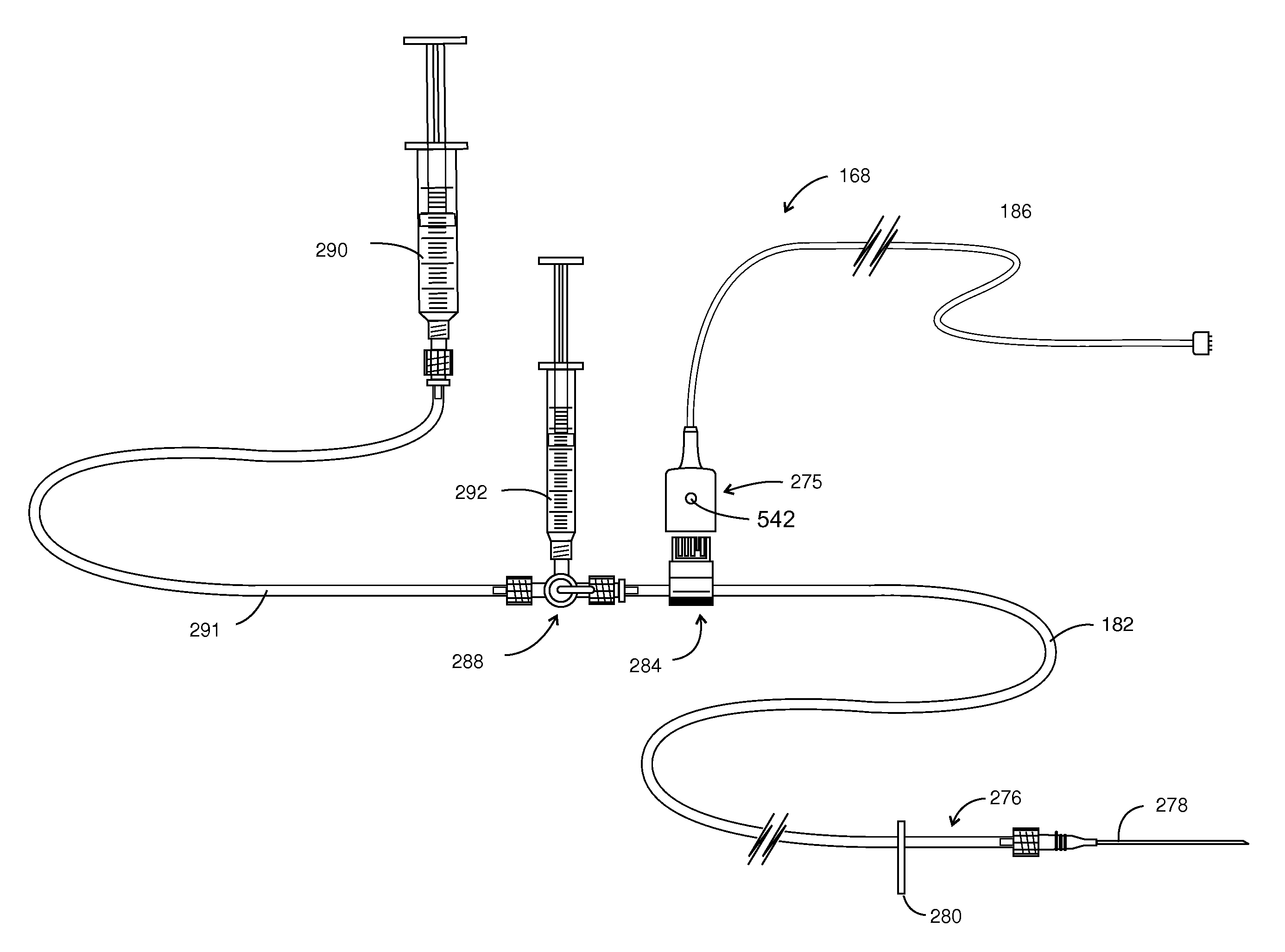
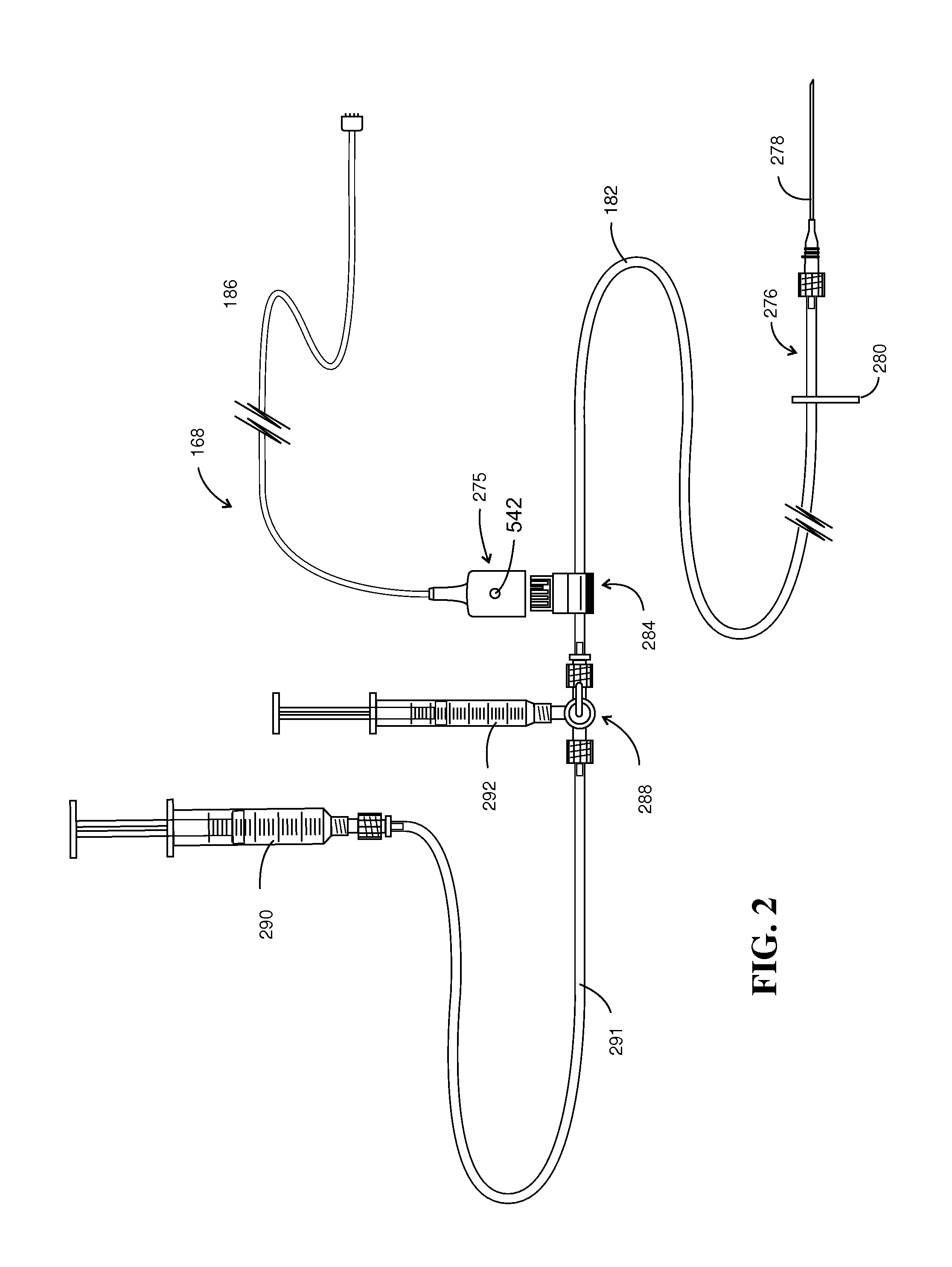
[0107]Referring to FIGS. 14 and 15, a dye flow detector 484 is revealed in enhanced detail. FIG. 14A shows two inter-connectable clamp housings 500 and 502 placed on either side of the portion of delivery tubing 504. Additionally, clamp-housing 502 is configured with 4 pins, two of which are seen at 508a and 508b. Two similar pins (not shown) are located on the opposite side of clamp housing 502. These pins are intended to be inserted within holes 510a-510b, within clamp housing 500. Note additionally that clamp housing 500 has a slot 512 formed therein, which provides connector registry. Device 484 performs in conjunction with a flexible circuit shown generally at 514. Flexible circuit 514 is retained in a wrap-around orientation by oppositely disposed support components 516 and 518.

[0108]Turning to FIG. 14C, the flexible circuit 514 is represented at a higher level of detail. In that figure, outboard printed circuit leads 520, 521 and 529 ex...

example 3

Optimization Parameters for Multi-Emitter / Detector Arrays

[0112]Following experimentation, including using animal models, it was determined that sensitivity of the sensor array could be improved by the implementation of multiple emitters and detectors in a sensor array. In order to utilize low concentrations of analyte, such as ICG, sensitivity is highly preferred for assaying organ function. Once a multiple emitter / detector sensor array was implemented, it was recognized that the overall system sensitivity was being hampered by the efficacy of the bandpass filter and collimating plates that were limited by cross talk between related channels in the sensor array. It should also be noted that such cross talk may be even more pronounced when utilizing reflectance mode excitations and detection. The interference filter is necessary in order to reduce incident light arising from the excitation lasers, with the detectors being tuned to detect light emitted as a result of fluorescence. Whe...


PUM


Abstract

A system, method and apparatus are disclosed for using a transcutaneous detection system to measure the quantity of a circulating organ activity detection analyte in the blood, and thereby assay the activity of an organ. A preferred organ for assay is the human liver and a preferred indicator is indocyanine green (ICG) dye The procedure is under the control of a monitor/controller having a visual display and capable of providing cues to the operator. A sensor array apparatus for use in conjunction with the system monitor/controller is configured for increased sensitivity of assaying organ function.

Description

CROSS-REFERENCE TO RELATED APPLICATIONS[0001]This application claims priority to pending U.S. Provisional Patent Application Ser. No. 61 / 528,562, filed Aug. 29, 2011, entitled “System for Non-Invasive Quantification of Liver Function” and claims priority to pending U.S. patent application Ser. No. 12 / 754,888, filed Apr. 6, 2010, entitled “Hemodynamic Detection of Circulatory Anomalies,” which is a continuation in part of and also claims priority to U.S. patent application Ser. No. 12 / 418,866, filed Apr. 6, 2009 and entitled “Hemodynamic Detection of Circulatory Anomalies,” the disclosures of which are incorporated by reference. The application also qualifies as an application under 35 U.S.C. §371 and claims the benefit of to pending PCT application No. PCT / US11 / 31433, filed Apr. 6, 2011 and published in English under PCT Article 21(2) the disclosure of which is also incorporated by reference.STATEMENT REGARDING FEDERALLY SPONSORED RESEARCH[0002]Not applicable.BACKGROUND[0003]The pre...

Claims


Application Information

Patent Timeline
Patent Type & Authority Applications(United States)
IPC IPC(8): A61B5/1455
CPCA61B8/481A61B5/0275A61B5/0071A61B5/4244A61B5/6816
Inventor EGGERS, PHILIP E.EGGERS, ERIC A.EGGERS, ANDREW R.MAYERCHAK, MARK A.
Owner CARDOX
Why Eureka
Try Eureka