Desmodronic shaft and yoke assembly for translating linear to rotary motion

Active Publication Date: 2013-01-03
EXODUS R&D INT PTE
View PDF3 Cites 0 Cited by
  • Summary
  • Abstract
  • Description
  • Claims
  • Application Information

AI Technical Summary

Benefits of technology

[0032]In preference the cam follower member and yoke structure inner surface are dimensioned such that the shaft rotates between 0 and 90 degrees without any such rotary movement being translated on rectilinear motion of the yoke structure. Thus, when applied to a combustion engine, the present invention improves combustion efficiency by also introducing a dwell time at top dead centre.
[00

Problems solved by technology

Nonetheless, time has proven that these types of internal combustion engines do have significant disadvantages and limitations.
The use of convention scotch yokes is not always possible for the most part as the piston stroke is short and the time available for drawing air into the combustion chamber is very short.
This causes combustion at less than the ideal 15 to 1 air/fuel ratio for the fuel which in turn, leaves unburnt fuel to be exhausted as pollutants into the a

Method used


Image

  • Desmodronic shaft and yoke assembly for translating linear to rotary motion
  • Desmodronic shaft and yoke assembly for translating linear to rotary motion
  • Desmodronic shaft and yoke assembly for translating linear to rotary motion

Examples


first embodiment

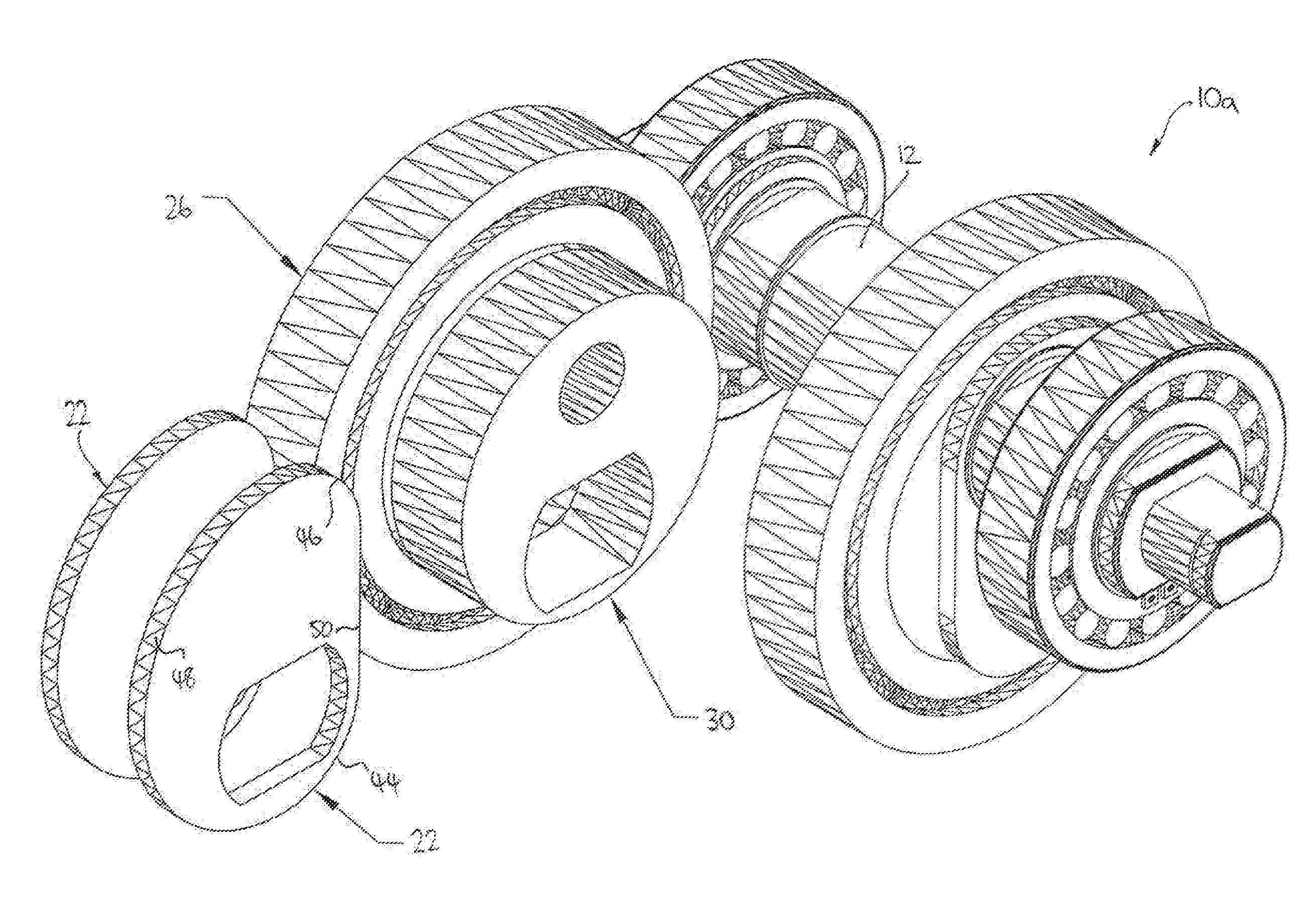
[0058]FIGS. 1-4 illustrate the present invention being an assembly 10a configured for single dwell from 0 through 90 degree rotation of the crank shaft 12, the assembly including a leverage means 14a having two cam follower members 22 built onto the crank shaft 12 and interacting with the yoke structure 18a such that force is carried from the yoke to rotate the crank.

[0059]In particular, the leverage means 14a includes two parallel and laterally spaced cam follower members 22 including arced surfaces adapted to contact respective inner surfaces 24 of the yoke structure 18a, the surfaces 24 being inner surfaces of the yoke structure located at the “base” of the yoke assembly 16a, that is, on the opposite end of the piston 20. The leverage means 14a further includes a large diameter rolling element or bearing 26 extending between the two cam follower members and adapted to contact an arced inner surface 28 of the yoke structure. Disposed inside the larger diameter rolling element 26 i...

second embodiment

[0075]Turning now to FIG. 8 and a preferred form of the invention, there is shown a leverage means 14c forming part of the assembly 10c shown in FIG. 9, the leverage means 14c including a similar cam follower member and yoke structure profile as depicted in the second embodiment but including a hollowed out channel 70 between which is rotatably mounted an internal roller 72. The roller is rotatable about a pin 73. A shaft including a cam follower configured like so and including an internal roller 72 is herein referred to as a desmodronic crank shaft.

[0076]FIGS. 9-10 illustrate the leverage means 14c in use with a linear yoke assembly 16c and it should be appreciated that the yoke structure is essentially the same as that discussed with respect to the second embodiment but having an inner surface configured slightly differently. It is to be understood that the inner surface still includes the main rounded edges of the second embodiment 60 and 62, as well as parallel surfaces 56 and ...

third embodiment

[0077]A further notable difference in this third embodiment is the sawn off portion 74 on the tip of the cam follower member at the junction between surfaces 46 and 48. The flat spot 74 allows for contact between the roller 70 and the inner peripheral edge 54 of the yoke at times when the tip of the member 14c, that is, the junction between surfaces 46 and 48, would otherwise have contacted the inner surface of the yoke, for example, throughout the dwell period of 0 through 90 degrees. The roller 70 thus serves to reduce friction and chatter between these surfaces at appropriate times throughout the 360 degree rotation of the crank.

[0078]In consideration of the drawings and above description, a person skilled in the art should appreciate how the assembly 10 of the invention works and provides various advantages over hitherto known assemblies which convert linear to rotary motion and vice versa. When applied to an internal combustion engine, where the linearly moveable member is a yo...


PUM


Abstract

The present invention relates to an assembly for translating linear movement to rotary motion, and in particular to an improved relationship between a linearly reciprocal member such as a yoke structure and associated piston, and a rotatable shaft such as a crank shaft. The invention could be used in any application where motion is to be translated from rotary to linear or vice versa, such as in compressors for example.

Description

CROSS-REFERENCE TO RELATED APPLICATIONS[0001]This application claims the benefit of an Australian provisional application number 2011902573, filed Jun. 30, 2011. The entire disclosure of the prior application is hereby incorporated by reference.FIELD OF THE INVENTION[0002]The present invention relates to an assembly for translating linear movement to rotary motion, and in particular to an improved relationship between a linearly reciprocal member such as a yoke structure and associated piston, and a rotatable shaft such as a crank shaft. The invention could be used in any application where motion is to be translated from rotary to linear or vice versa, such as in compressors for example.BACKGROUND OF THE INVENTION[0003]The internal combustion engine has now been with us for many decades and has become a most familiar design wherein the reciprocating piston uses connecting rods to connect the piston to the crank pins of the crank shaft to translate linear reciprocating motion of the ...

Claims


Application Information

Patent Timeline
IPC IPC(8): F02B75/32F16H25/08
CPCF02B75/32F16H21/30Y10T74/1828F01B9/023F01B9/00F01B9/06F01B9/02F02B75/12F02B2275/36F16H21/36
Inventor FLENCHE, GEORGE
Owner EXODUS R&D INT PTE
Why Eureka
Try Eureka