


Quick Research
Generate reliable direction feasibility study reports for your R&D in just a few steps.

Technical Q&A
Discover and master advanced knowledge NOW. Basics, ideas, possibilities, all at once.

Find Solutions
As an expert in R&D theories, this can generate solutions to your technical problems instantly.

Evaluate Feasibility
Analyze your overall solution with one click, know your potential R&D risks in advance.

Monitor Landscape
Get weekly tech updates, stay abreast of the latest tech innovations and key insights.
Carbon membrane structure and method for producing same
- Summary
- Abstract
- Description
- Claims
- Application Information
AI Technical Summary
Benefits of technology
Problems solved by technology
Method used
Image

Examples
example 1
Production of Porous Support Body
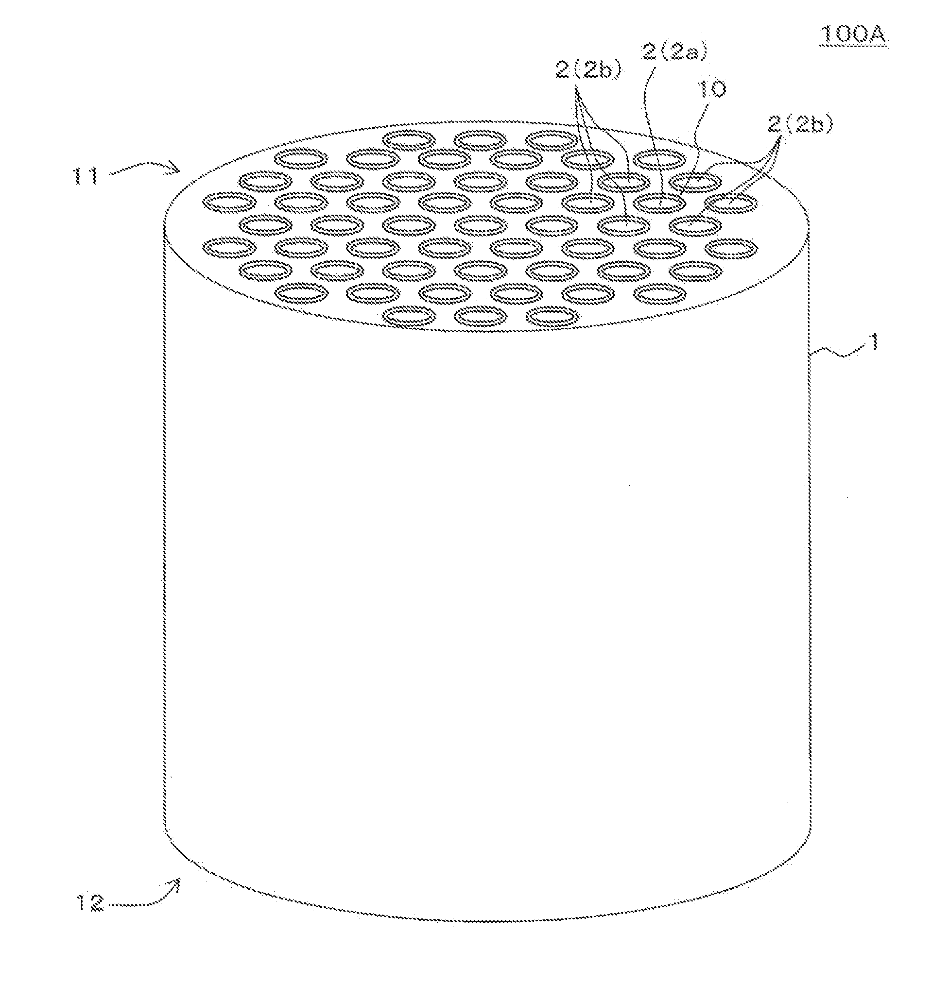
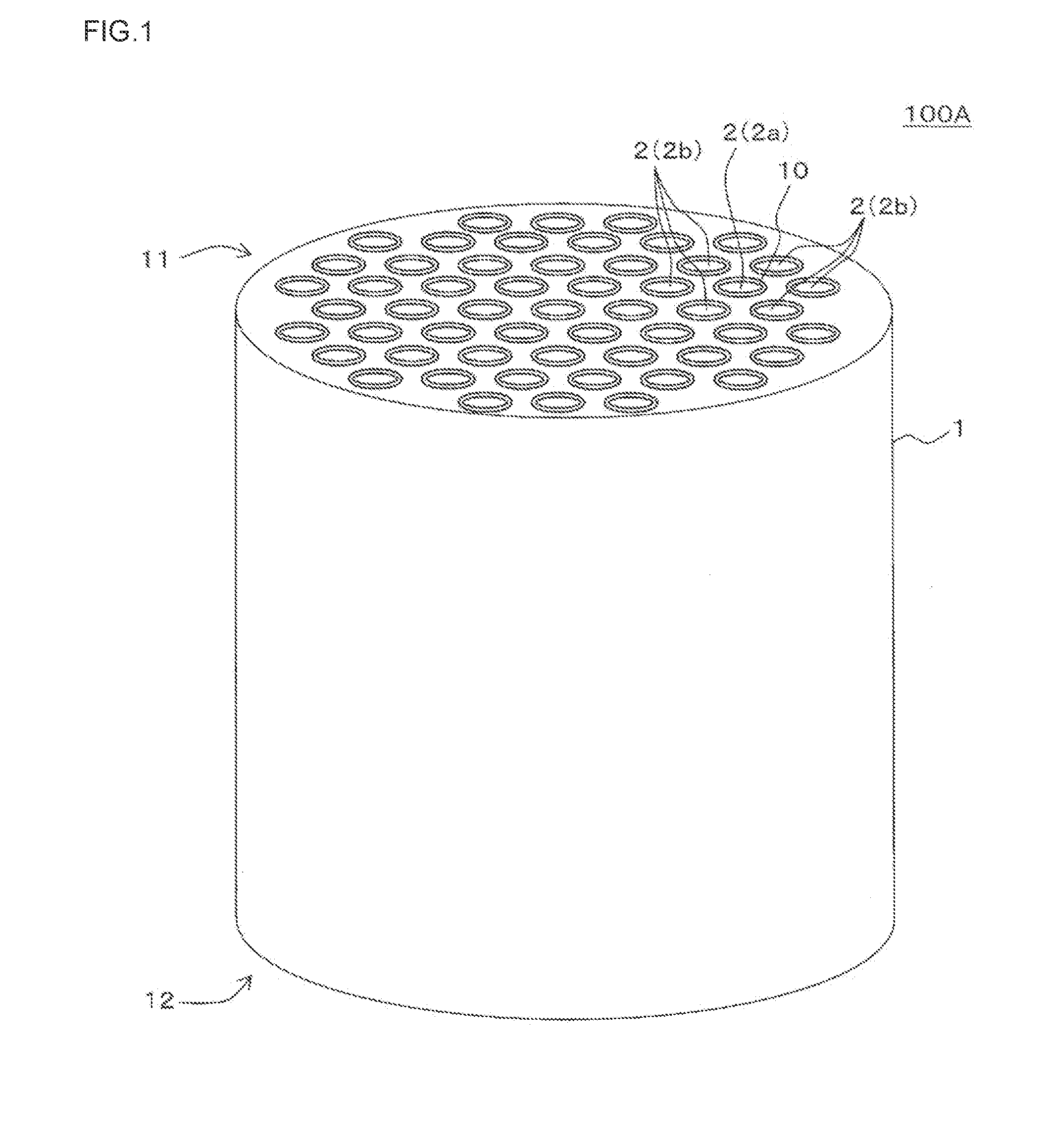
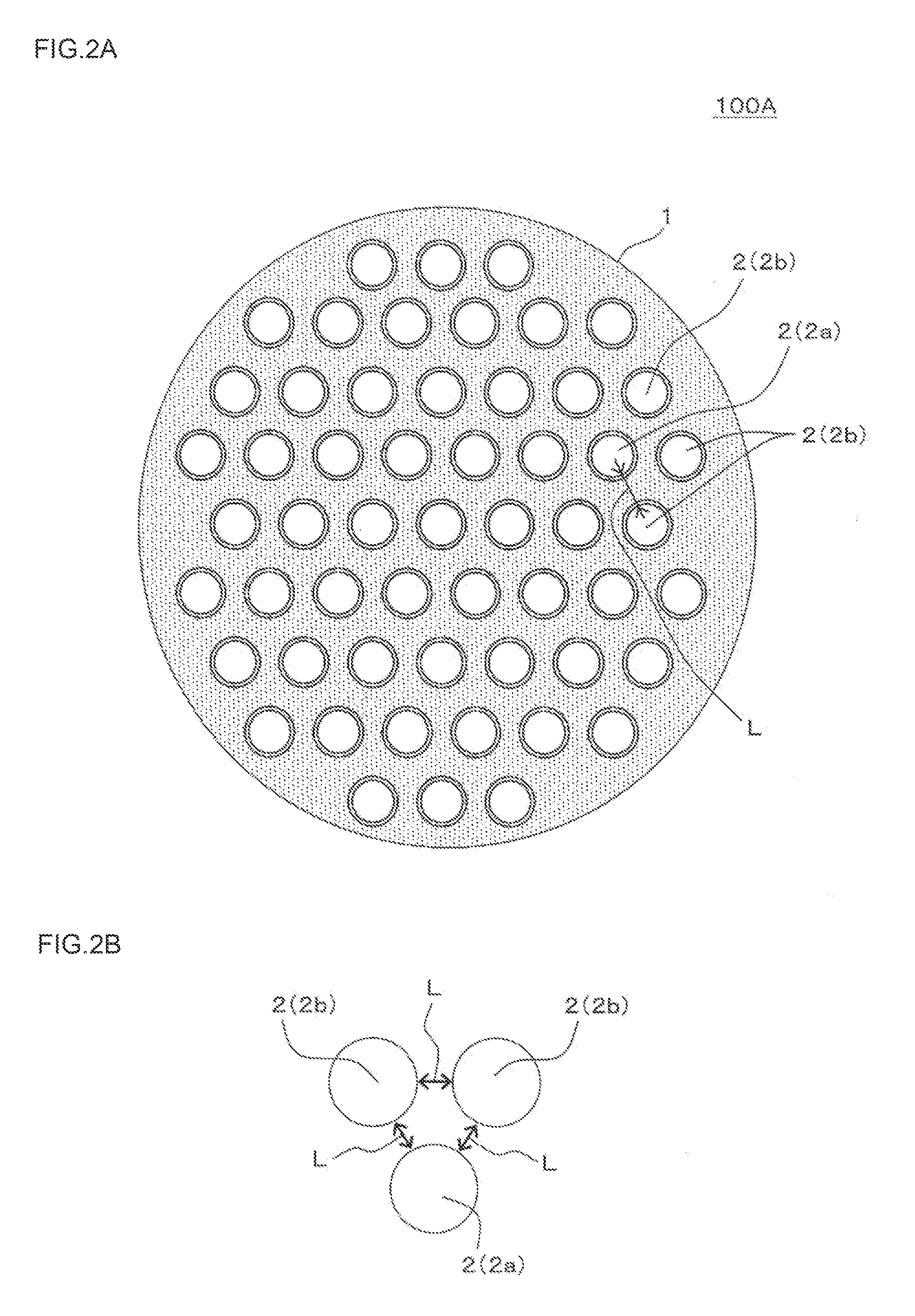
[0119]The porous support body passed through the formation by extrusion and the firing to produce a monolith-shaped alumina porous substrate having an average pore size of 20 μm and a porosity of 40%. Then, an alumina intermediate layer having a thickness of 150 μm was formed on the inner wall faces of the cells in the substrate obtained above. Then, on the intermediate layer, an alumina surface layer having a thickness of 10 μm and an average pore size of 0.1 μm was formed to obtain a porous support body. In Example 1, 55 cells having a diameter of 2.80 mm were formed, and the length of the gap L between adjacent cells was 0.60 mm. The aforementioned “gap L between adjacent cells” means the distance L from one cell to another cell adjacent to the one cell (see, e.g., FIG. 2B) and shortest distance between the one cell and another cell adjacent to the one cell. In Example 1, the outer diameter of the porous support body was 30 mm, and the length in t...
examples 2 to 34
Production of Porous Support Body
[0129]A carbon membrane structure was produced in the same manner as in Example 1 except that the distance between cells (mm) (the distance between cells means the distance L from one cell to another cell adjacent to the one cell), the membrane formation number (times), the polyamide acid concentration (mass %), the viscosity (mPa·s), the monolith external shape, the cell shape, the cell pitch (mm), the cell diameter (mm), the cell number (cells), and the cell arrangement were changed as shown in Tables 1 to 7 to make an evaluation on the separation performance of each carbon membrane. The evaluation results are shown in Tables 10 to 18. The cell pitch (mm) means the distance between the centers of adjacent cells. In Tables 1 to 7, a figure corresponding to the shape of the carbon membrane structure is shown as “corresponding figure of the carbon membrane structure”, and the carbon membrane structure having a shape shown in the figure was used. Regar...
examples 35 to 40
Production of Porous Support Body
[0134]In Example 35, the porous support body was produced in the same manner as in Example 1. In Example 35, 55 cells having a diameter of 2.80 mm were formed, and the length of the gap L between adjacent cells was 0.60 mm. In Example 35, the outer diameter of the porous support body was 30 mm, and the length in the cell extension direction was 160 mm. A glass paste was applied to both the end faces of the porous support body produced in this manner and fired at 950° C. for three hours to form a sealing portion, thereby sealing airtightly.
[0135]In Example 36, there was produced a porous support body in the same manner as in Example 35 except that the distance (mm) between cells and the cell diameter (mm) were changed as shown in Table 8.
[0136]In Examples 37 to 40, slits as shown in FIGS. 7C and 7D were formed in the porous support body. Specifically, slit-shaped gaps were formed by cutting away a part of the plural cell rows so that apart of the cell...
PUM
| Property | Measurement | Unit |
|---|---|---|
| Thickness | aaaaa | aaaaa |
| Diameter | aaaaa | aaaaa |
| Viscosity | aaaaa | aaaaa |
Abstract
Description
Claims
Application Information
 - R&D Engineer
- R&D Manager
- IP Professional
- Industry Leading Data Capabilities
- Powerful AI technology
- Patent DNA Extraction
Browse by: Latest US Patents, China's latest patents, Technical Efficacy Thesaurus, Application Domain, Technology Topic, Popular Technical Reports.
© 2024 PatSnap. All rights reserved.Legal|Privacy policy|Modern Slavery Act Transparency Statement|Sitemap|About US| Contact US: help@patsnap.com