
Varactor and Method for Producing a Varactor

a varactor and varactor technology, applied in capacitor manufacture, capacitors with temperature varied dielectrics, capacitors, etc., can solve the problems of low loading capacity, low quality factor of semiconductor diode varactors, limited capacitance range, etc., and achieve the effect of reducing the sintering temperatur

Active Publication Date: 2013-01-03
EPCOS AG
View PDF2 Cites 4 Cited by
  • Summary
  • Abstract
  • Description
  • Claims
  • Application Information

AI Technical Summary

Benefits of technology

This patent describes a method for improving the performance of capacitors in a microwave device. The method involves using a second dielectric layer to separate the capacitor region from the underlying layers, which prevents interference between them. This allows for better heating of the capacitor region and reduces dielectric loss. The first dielectric layer is doped to further improve its performance. The symmetrical construction of the device ensures uniform heating and prevents temperature gradients. Additionally, a fully impermeable intermediate layer prevents dopants from migrating and impairing the functionality of the capacitor region. These improvements make the microwave device more reliable and efficient.

Problems solved by technology

A widespread problem of varactors is that of obtaining a good tunability with regard to the dielectricity.
Semiconductor diode varactors have only a low quality factor, a low loading capacity and a limited capacitance range.

Method used


Image

  • Varactor and Method for Producing a Varactor
  • Varactor and Method for Producing a Varactor
  • Varactor and Method for Producing a Varactor

Examples


Embodiment Construction

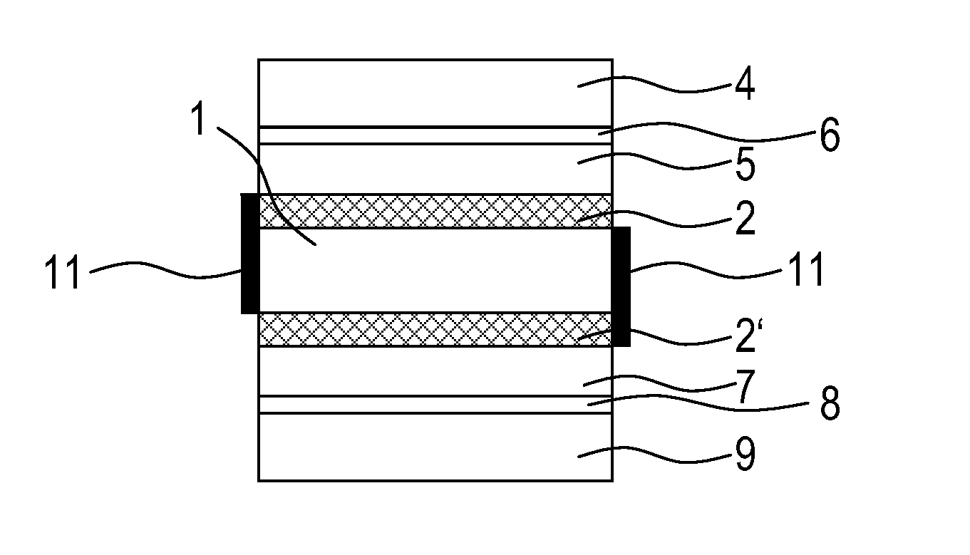
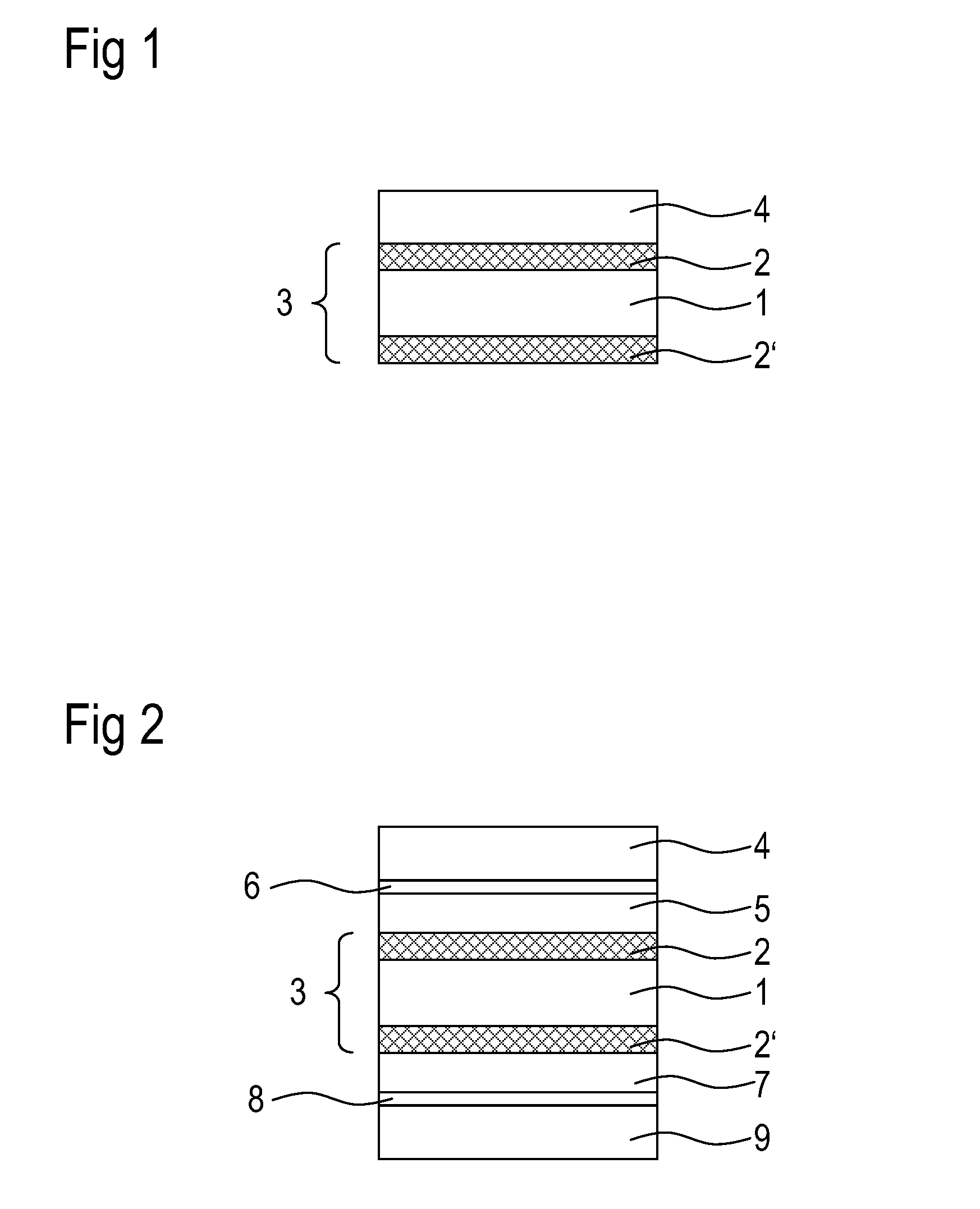
[0117]FIG. 1 shows an exemplary embodiment of a varactor according to the invention in schematic cross section. This exemplary embodiment comprises a capacitor region 3, which comprises a first dielectric layer 1, on the top side of which a first electrode 2 is arranged and on the underside of which a second electrode 2′ is arranged. A first PTC region 4 is arranged on the first electrode 2. As a result of the application of a bias voltage to the first PTC region 4, heat is generated in the latter, said heat being forwarded to the first dielectric layer 1 via the first electrode 2. As a result of the supply of heat into the first dielectric layer 1, the capacitance of the capacitor region 3 can be altered.

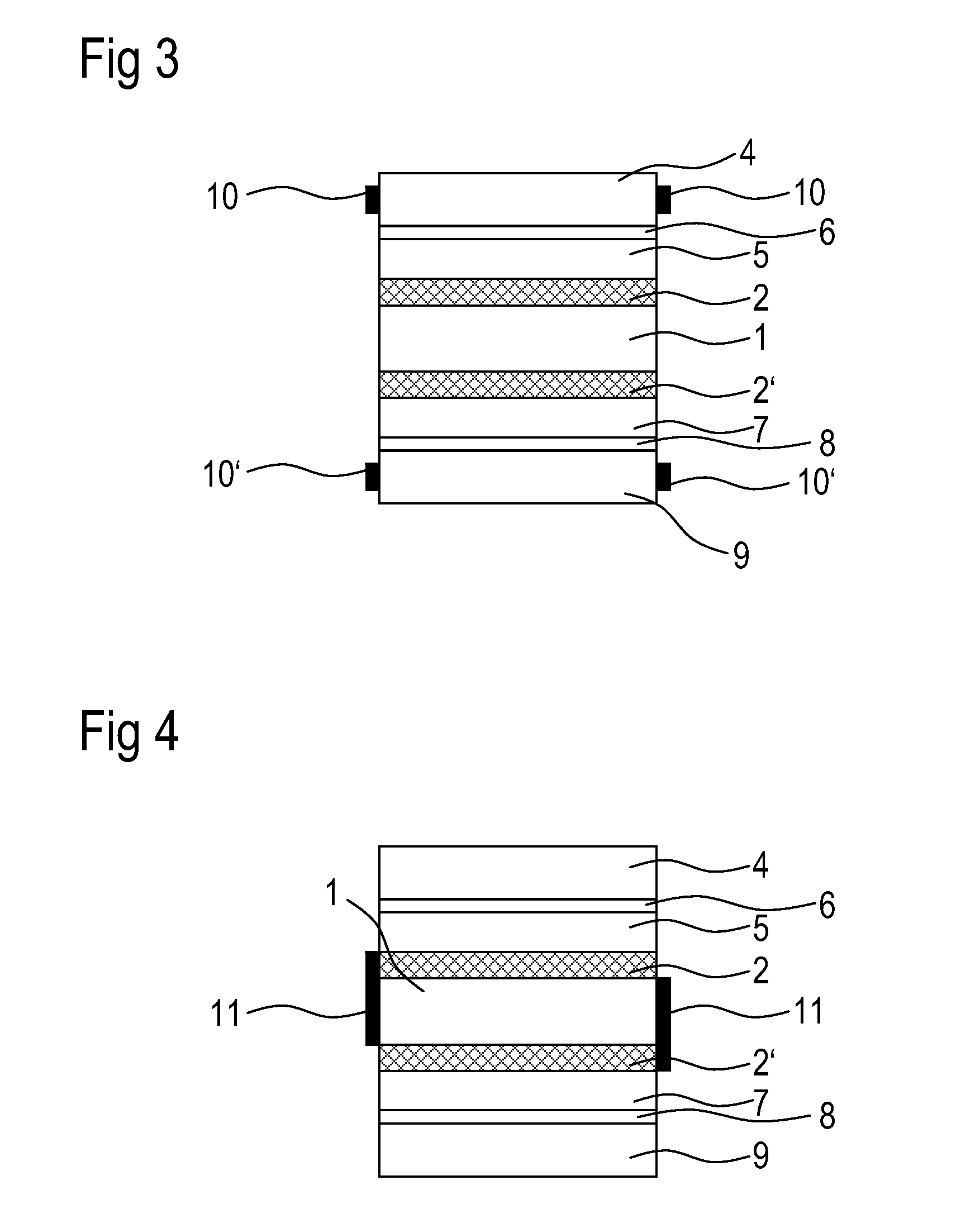
[0118]FIG. 2 shows, in schematic cross section, a further exemplary embodiment of a varactor, which exemplary embodiment has a symmetrical construction with respect to the first dielectric layer 1. In this case, the varactor comprises the following layers / regions: a second PTC regi...


PUM

PropertyMeasurementUnit
thicknessaaaaaaaaaa
thicknessaaaaaaaaaa
thicknessaaaaaaaaaa

Abstract

A varactor includes a first PTC region, which comprises a ceramic material with a positive temperature coefficient with respect to the resistance. The varactor also includes a capacitor region that includes a first electrode, a second electrode, and a first dielectric layer arranged between the first electrode and the second electrode. The first PTC region and the capacitor region are connected thermally conductively to one another. The capacitance of the capacitor region can be changed by applying a bias to the first PTC region, the capacitor region or to the first PTC region and the capacitor region.

Description

[0001]This patent application is a national phase filing under section 371 of co-pending International Application No. PCT / EP2010 / 070422, filed Dec. 21, 2010, which designated the United States and was not published in English, and which claims priority to German Application No. 10 2009 059 873.1, filed Dec. 21, 2009, both of which applications are incorporated herein by reference.TECHNICAL FIELD[0002]The present invention relates to a varactor and a method for producing a varactor.BACKGROUND[0003]A widespread problem of varactors is that of obtaining a good tunability with regard to the dielectricity.[0004]Varactors are voltage-tunable capacitors in which the capacitance is dependent on a voltage applied thereto, or the capacitance can be altered by a change in the applied voltage. Varactors are employed for example in radiofrequency circuits in which electrical tuning takes place, such as, for example, in filters or phase shifters. Varactors can be used as frequency filters, for e...

Claims


Application Information

Patent Timeline
Patent Type & Authority Applications(United States)
IPC IPC(8): H01G7/06H01G13/00
CPCH01G7/04Y10T29/435H01G7/06
Inventor TESTINO, ANDREA
Owner EPCOS AG
Learn More