Hydrogen generation system and method for generating hydrogen for mobile and power generator

a technology of hydrogen generation system and power generator, which is applied in the direction of electrochemical generators, machines/engines, mechanical equipment, etc., can solve the problems of high cost, low efficiency of nuclear power generation, and difficulty in producing stable output, so as to ensure the safety of formic acid and ensure the stability of formic acid production, the effect of continuously generating hydrogen from formic acid

Inactive Publication Date: 2013-01-03
FORMIC ACID HYDROGEN ENERGY DEV CORP
View PDF4 Cites 11 Cited by
  • Summary
  • Abstract
  • Description
  • Claims
  • Application Information

AI Technical Summary

Benefits of technology

[0026]According to the hydrogen generation system due to the present invention, it is possible to safely accommodate formic acid as a storage tank of hydrogen and to extract hydrogen from the formic acid in case of need for its supply to a desired destination. It is also possible to continuously generate hydrogen from formic acid at low cost while supplying formic acid to the hydrogen generation reaction section and while repeatedly using the ionic liquid.
[0027]Thus the hydrogen generation system invented here can be loaded onto hydrogen fuel vehicles, such as those equipped with a hydrogen engine and / or a fuel cell that need a hydrogen source.
[0028]As described above, in this case formic acid (in the liquid state at normal temperature) serves as a hydrogen storage tank in the hydrogen generation system. Compared with the form of high pressure hydrogen gas stored in a cylinder and the form of hydrogen liquid contained in a very low temperature cylinder, the hydrogen generation system due to this invention is more useful for mobiles and automobiles like hydrogen fuel cars because of the safe, compact, and low-cost hydrogen storage form.
[0029]Furthermore, the hydrogen generation system invented here can be connected to commercial or home fuel cells and to a hydrogen turbine (hydrogen combustion turbine) as a hydrogen supply source. In addition, the hydrogen generation system due to the present invention can constitute a cogeneration system that performs hot water supply, heating, power generation, and the like with the heat energy accompanying power generation by a fuel cell or hydrogen turbine.
[0030]By the hydrogen generation method invented here it is possible to solve such hydrogen problems as the production cost, safety, cost, and storage efficiency that are met in the industry-scale generation of hydrogen.

Problems solved by technology

However, the nuclear power generation holds a risk of radiation leak.
However, power generation using such natural energy resources is low-efficiency, high-cost, and difficult to produce a stable output.
However, high-pressure cylinders are mainly used for storage and transport of hydrogen, posing problems in safety and the storage (low capacity).
In addition, on an industrial scale, hydrogen is usually produced through electrolysis of water, raising a problem also in production cost.

Method used


Image

  • Hydrogen generation system and method for generating hydrogen for mobile and power generator
  • Hydrogen generation system and method for generating hydrogen for mobile and power generator
  • Hydrogen generation system and method for generating hydrogen for mobile and power generator

Examples


embodiment 1

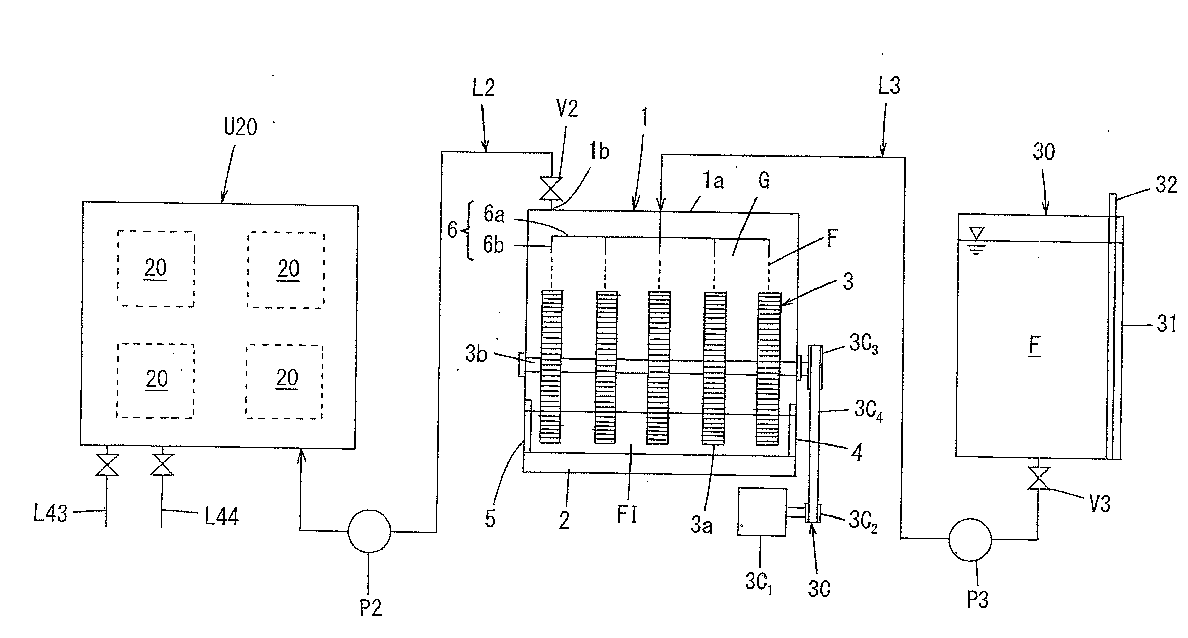
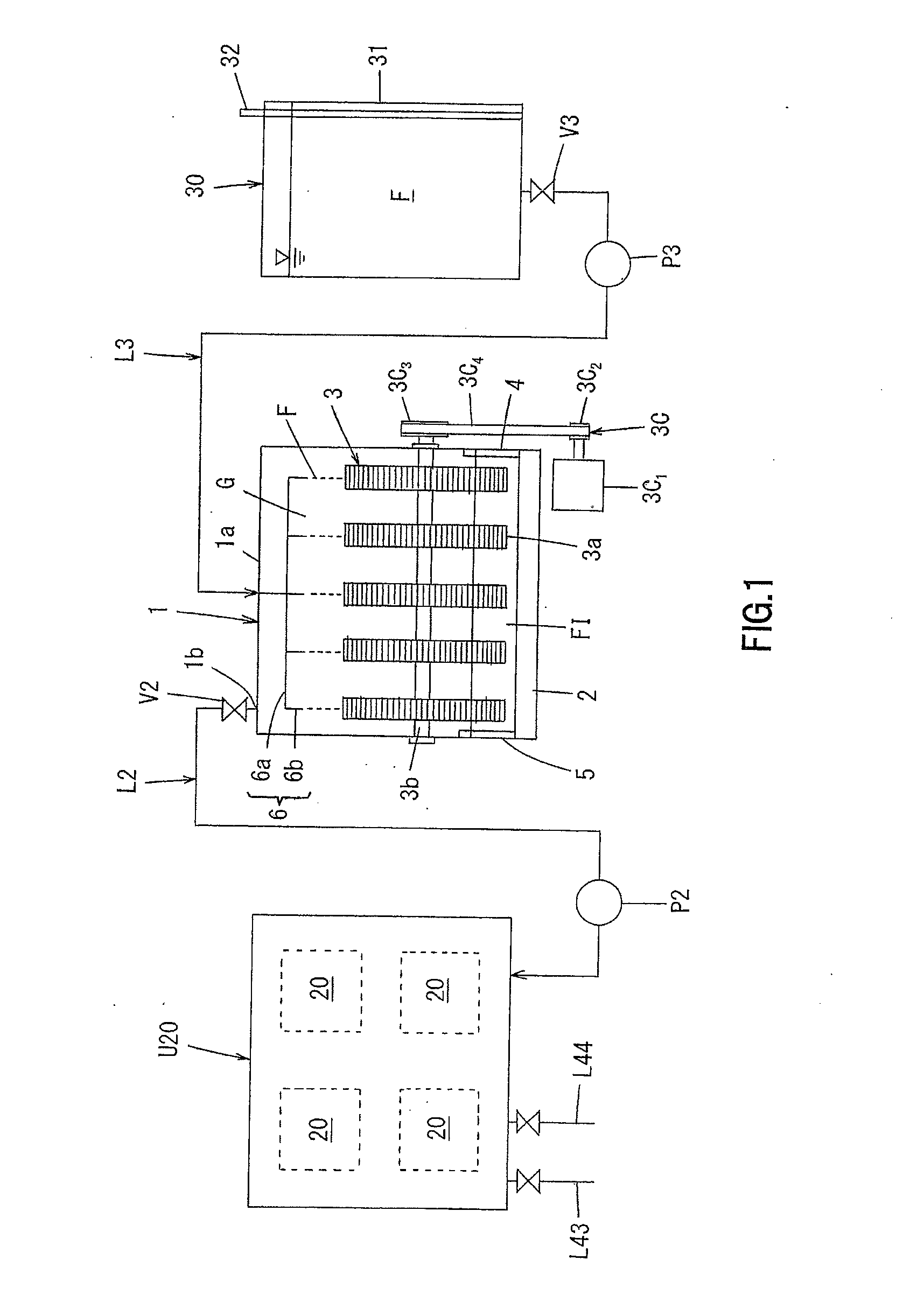
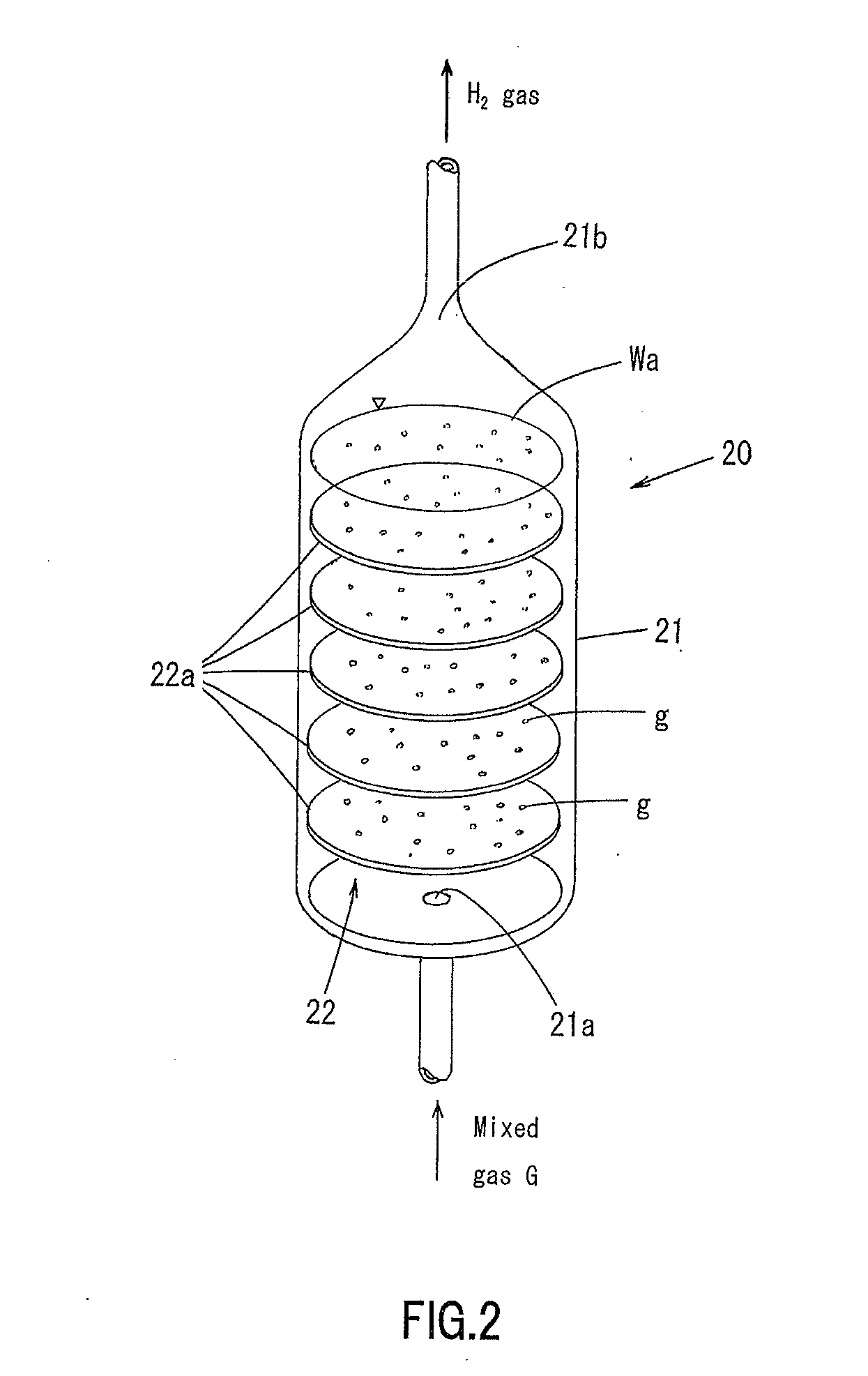
[0104]FIG. 1 is a schematic configuration diagram illustrating Embodiment 1 of a hydrogen generation system due to the present invention. FIG. 2 is a perspective view illustrating a separation section in Embodiment 1 of the hydrogen generation system. FIG. 3 is a schematic configuration diagram illustrating a plurality of separation sections in Embodiment 1 of the hydrogen generation system. FIG. 4 is a schematic configuration diagram illustrating a plurality of separation sections and a water temperature adjustment mechanisms in Embodiment 1 of the hydrogen generation system. FIG. 5 is a block diagram illustrating a control system of Embodiment 1 of the hydrogen generation system. FIG. 6 is a conception diagram illustrating a hydrogen fuel vehicle including Embodiment 1 of the hydrogen generation system due to the present invention. FIG. 7 is the first diagram illustrating an example of an operation flow of a hydrogen generation system due to the present invention in the hydrogen f...

embodiment 2

[0188]FIG. 10 is a schematic configuration diagram illustrating Embodiment 2 of the hydrogen generation system due to the present invention. FIG. 11A is a side view illustrating a configuration of a spreading section in Embodiment 2 of the hydrogen generation system, and FIG. 11B is a front view of the spreading section. FIG. 12A is a side view illustrating a configuration of another spreading section in a hydrogen generation reaction section in Embodiment 2 of the hydrogen generation system, and FIG. 12B is a front view of the spreading section. In FIG. 10, the same components as those in FIG. 1 are represented by the same reference numerals.

[0189]Embodiment 2 of the hydrogen generation system has the same configurations as Embodiment 1 except for the configuration of the hydrogen generation reaction section. Hereinafter, differences of Embodiment 2 from Embodiment 1 will be described mainly.

[0190]Specifically, a hydrogen generation reaction section 10 includes a hermetically-seala...

embodiment 3

[0202]FIG. 13 is a schematic configuration diagram illustrating Embodiment 3 of the hydrogen generation system due to the present invention. FIG. 14 a schematic perspective view illustrating a hydrogen generation reaction section in Embodiment 3 of the hydrogen generation system (top panel not shown). In FIGS. 13 and 14, the same components as those in FIG. 10 are represented by the same reference numerals, and description thereof will be omitted.

[0203]Embodiment 3 has the same configurations as Embodiment 2 except mainly for the configuration and the number of hydrogen generation reaction sections 110. Hereinafter, differences of Embodiment 3 from Embodiment 2 will be described mainly.

[0204]Embodiment 3 of the hydrogen generation system includes three hydrogen generation reaction sections 110. In this configuration, formic acid is supplied from one formic acid storage section 30 to the respective hydrogen generation reaction sections 110 through the respective pipe lines L3, and th...


PUM

PropertyMeasurementUnit
temperatureaaaaaaaaaa
viscosityaaaaaaaaaa

Abstract

A hydrogen generation system includes a hydrogen generation reaction section for containing a liquid mixture of formic acid and an ionic liquid, and decomposing the formic acid into hydrogen and carbon dioxide by heating; and a separation section for separating a mixture of hydrogen and carbon dioxide supplied from the hydrogen generation reaction section into hydrogen and carbon dioxide, wherein after the separation, the hydrogen is sent out of the separation section to an external hydrogen destination, and the carbon dioxide is sent out of the separation section to an external carbon dioxide destination or emitted into the atmosphere.

Description

CROSS-REFERENCE TO RELATED APPLICATIONS[0001]This application is related to Japanese Patent application No. 2011-145992, filed on 30 Jun., 2011 whose priority is claimed under 35 USC §119, the disclosure of which is incorporated by reference in its entirety.BACKGROUND OF THE INVENTION[0002]1. Field of the Invention[0003]The present invention relates to a hydrogen generation system that generates hydrogen in the presence of an ionic liquid and to a method for generating hydrogen, a mobile (mobile object) and a power generator using or including the system.[0004]2. Description of the Related Art[0005]In recent years, there has been a growing problem of global warming, and as causes thereof, ozone layer depletion and increasing carbon dioxide emission due to combustion of fossil fuel have been pointed out.[0006]As alternative energy sources that can reduce carbon dioxide emission, nuclear fuel, solar power, wind power, water power, methanol, methane hydrate, and hydrogen have been attr...

Claims


Application Information

Patent Timeline
Patent Type & Authority Applications(United States)
IPC IPC(8): C01B3/22B01J7/00F02G3/00H01M8/06H01M16/00C01B32/50
CPCB01J19/1887B01J2219/00231C01B2203/0272C01B2203/0277C01B2203/0415C01B2203/0475C01B2203/1064C01B2203/1211B01J19/0066B01J2219/00006B01J2219/0011B01J2219/00182B01J2219/002B01J2219/00213C01B3/22
Inventor NAKAHARA, MASARU
Owner FORMIC ACID HYDROGEN ENERGY DEV CORP
Why Eureka
Try Eureka