Multi-focal optical component, optical system, and imaging method

a multi-focal, optical component technology, applied in the field of optical imaging, can solve the problems of not having the capability of optical zooming, the practicability of mpm-e probes, and the difficulty of achieving so as to achieve the same capability in a compact endoscope, the effect of reducing the field of view and reducing the resolution

Active Publication Date: 2013-01-03
CORNELL UNIV - CORNELL CENT FOR TECH ENTERPRISE & COMMERICIALIZATION CCTEC
View PDF5 Cites 11 Cited by
  • Summary
  • Abstract
  • Description
  • Claims
  • Application Information

AI Technical Summary

Benefits of technology

[0011]An embodiment of the invention is a method for obtaining an image of an object. The method includes providing a multi-photon endoscope including a scanner operably disposed therein and an optical lens disposed in a distal end of the endoscope, wherein the lens has a lens body that transmits light in an optical path there through, further wherein the lens body consists of an anterior surface, a posterior surface, and a medium there between, further wherein one of the anterior surface and the posterior surface has a single curvature and the other of the anterior surface and the, posterior surface has at least two optical zones each having a different curvature; propagating light from the scanner through one of the at least two optical zones of the lens to focus the light at a focus location; and propagating light from the scanner through a different one of the at least two optical zones of the lens to focus the light at a different focus location. In a non-limiting aspect, the method further includes propagating light from the scanner through another different one of the at least two optical zones of the lens to focus the light at another different focus location. In a non-limiting aspect, propagating light from the scanner through one of the at least two optical zones of the lens to focus the light at a focus location comprises obtaining a higher resolution, lower field of view image of an object, and propagating light from the scanner through a different one of the at least two optical zones of the lens to focus the light at a different focus location comprises obtaining a lower resolution, larger field of view image of the object.

Problems solved by technology

A significant obstacle to the development of a practical MPM-E probe has been the need for optical zooming capability.
While such an optical zooming capability is easily accomplished with conventional microscopes by using multiple objective lenses, achieving the same capability in a compact endoscope presents a significant challenge.
However, these endoscope probes do not provide optical zooming capability, although by scanning a small area using a galvo mirror or fiber scanner, magnified images could be obtained.
Therefore, previous systems were limited to performing either high-resolution imaging with a small FOV or low-resolution imaging with a large FOV.

Method used


Image

  • Multi-focal optical component, optical system, and imaging method
  • Multi-focal optical component, optical system, and imaging method
  • Multi-focal optical component, optical system, and imaging method

Examples


Embodiment Construction

[0025]Reference will now be made in detail to the present exemplary embodiments of the invention, examples of which are illustrated in the accompanying drawings. Wherever possible, the same reference numbers will be used throughout the drawings to refer to the same or like parts.

[0026]An embodiment of the invention is directed to an optical lens having at least two optical zones over its surfaces such that input light can be focused at at least two locations along an optical axis of the lens.

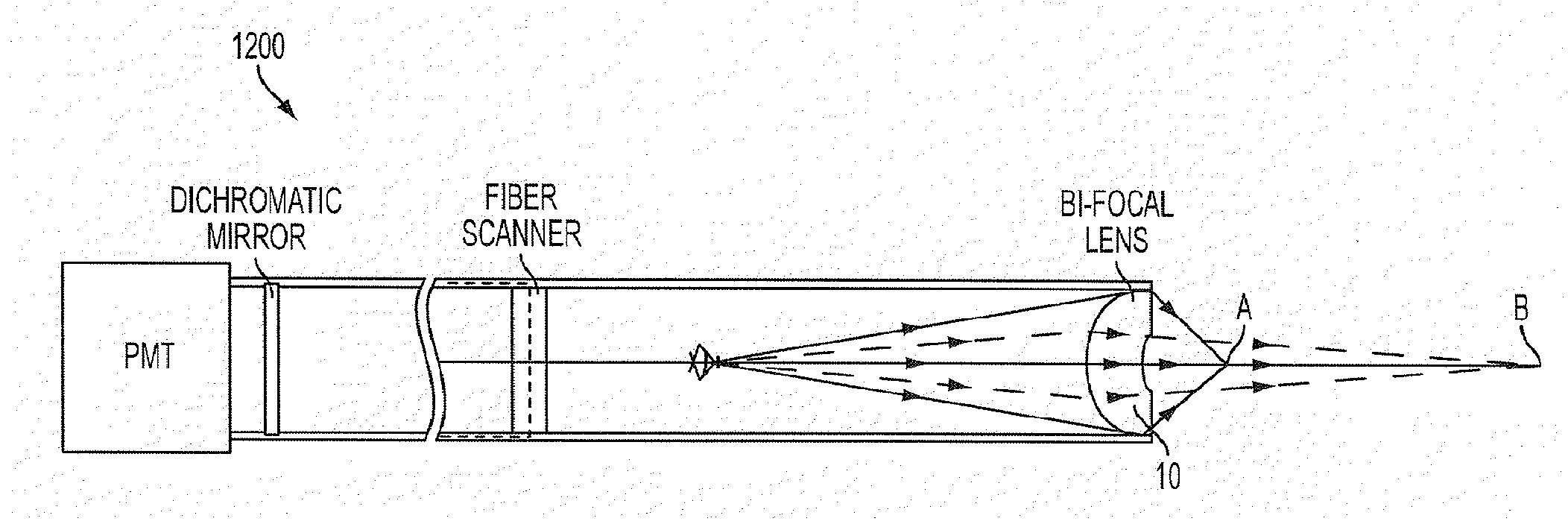
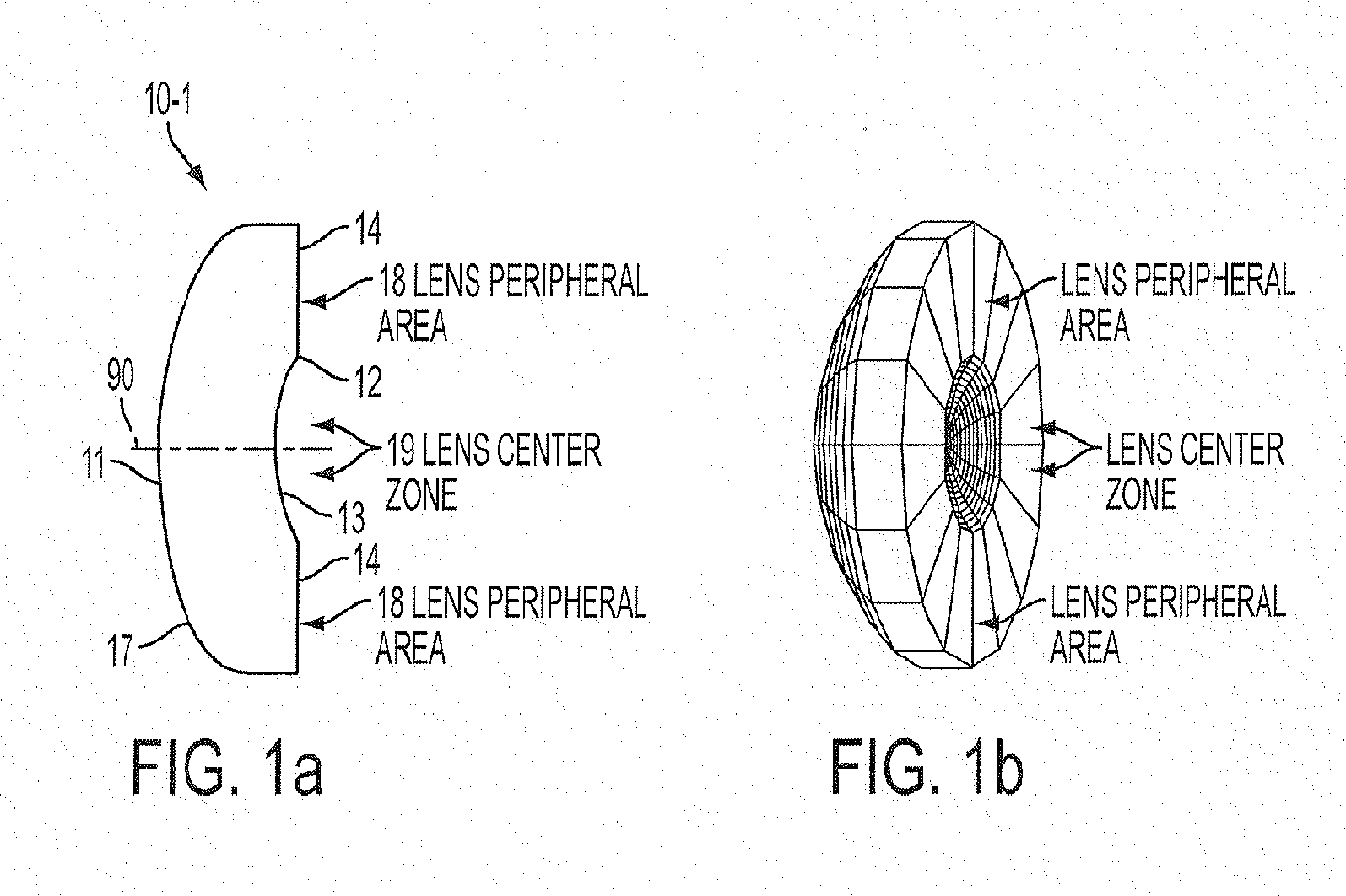
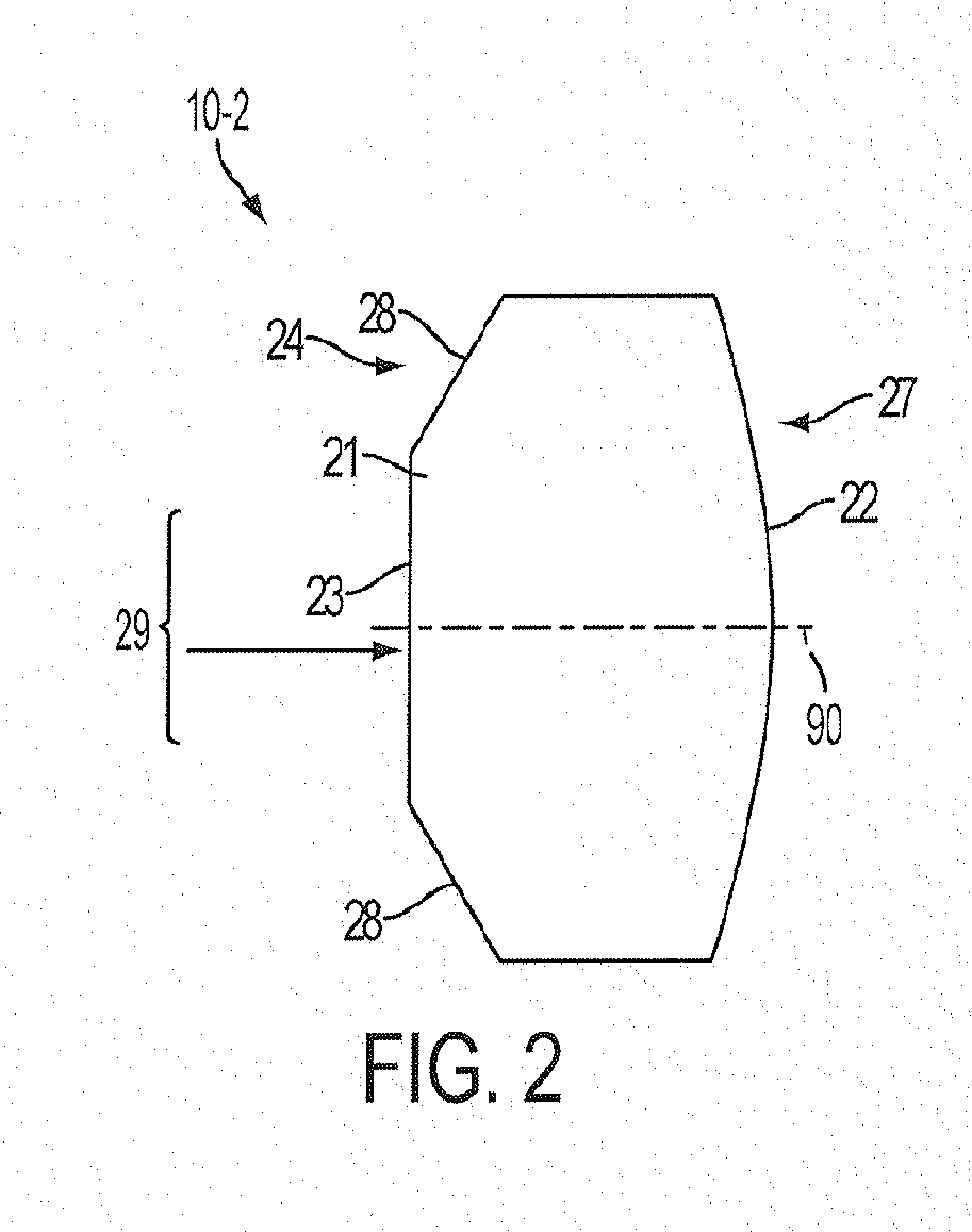
[0027]FIG. 1(a) shows the cross sectional profile of an exemplary lens 10-1. The lens 10-1 has an anterior surface 11 and a posterior surface 12 (assuming input light from the left) and an optical axis 90 as shown. The anterior surface 11 has a single convex curvature 17 over its entire surface; however, the surface may be aspheric. The posterior surface 12 has a center region 19 having a concave curvature 13 and a peripheral region 18 having a planar curvature 14. The central region provides th...


PUM


Abstract

An optical lens comprising a lens body that transmits light in an optical path there through, wherein the lens body consists of an anterior surface, a posterior surface, and a medium there between, further wherein one of the anterior surface and the posterior surface has a single curvature and the other of the anterior surface and the posterior surface has at, least two optical zones each having a different curvature. An optical system, comprising a multi-photon endoscope having a distal end, and the optical lens disposed in the distal end. A method for obtaining an image of an object comprising providing the multi-photon endoscope, propagating light from the endoscope scanner one optical zone of the lens to focus the light at a focus location, and propagating light from the scanner through a different optical zones of the lens to focus the light at a different focus location.

Description

CROSS-REFERENCE TO RELATED APPLICATIONS[0001]This application claims priority to U.S. Provisional application Ser. No. 61 / 297,551 filed on Jan. 22, 2010, the subject matter of which is incorporated herein by reference in its entirety to the fullest allowable extent.BACKGROUND OF THE INVENTION[0002]1. Field of the Invention[0003]Embodiments of the invention generally pertain to the field of optical imaging, more particularly to endoscopic apparatus / systems that can simultaneously acquire lower field of view (FOV), higher resolution images and wider FOV, lower resolution images and, most particularly to single, multi-focal optical components that enable simultaneous lower FOV, higher resolution imaging and wider FOV, lower resolution imaging, and use of such components in endoscopes and particularly multi-photon endoscopes (MPEs).[0004]2. Description of Related Art[0005]Multiphoton microscopy (MPM) is a powerful tool for biological imaging. It enables minimally invasive imaging of end...

Claims


Application Information

Patent Timeline
Patent Type & Authority Applications(United States)
IPC IPC(8): G02B3/10A61B1/002
CPCA61B1/00188G02B23/2423G02B21/0028A61B1/00172A61B1/043A61B5/0068A61B5/0084G02B3/10
Inventor WEBB, WATT W.CHEN, MINGHAN
Owner CORNELL UNIV - CORNELL CENT FOR TECH ENTERPRISE & COMMERICIALIZATION CCTEC
Why Eureka
Try Eureka