Method for manufacturing a birefringent microstructured optical fiber

a microstructured optical fiber and manufacturing method technology, applied in the field of fiber optics, can solve the problem that the microstructure does not support the manufacture of birefringent optical fibers, and achieve the effect of increasing the diameter and mass of the preform

Inactive Publication Date: 2013-01-10
CLOSED PROFOTECH CJSC PROFOTECH
View PDF16 Cites 13 Cited by
  • Summary
  • Abstract
  • Description
  • Claims
  • Application Information

AI Technical Summary

Benefits of technology

[0031]Step g) comprises sealing at least one end and preferably both ends of the preform segment. Similarly to step c), the sealing can be accomplished by a localized heating device, such as a gas burner. The sealing step attaches the preform segment to the surrounding tube and prevents ingress of impurities, foreign fumes and gases into the internal channels.
[0032]Step h) comprises assembling the preform segment with a capillary tube carrying a tubular process holder. In step i) the preform segment and the capillary tube are joined on a side opposite to the tubular process holder. A non-detachable joint between the preform segment and the capillary tube can be accomplished by fusing, for example. A gap may be left on the opposite end between the internal surface of the capillary quartz tube and the preform segment. A benefit of this process step is that the preform is conveniently secured for the following fiber drawing step. Furthermore, the diameter and mass of the preform are increased which is why this step enables manufacture of optical fibers of virtually any desired diameter.

Problems solved by technology

Such a microstructure does not support manufacture of birefringent optical fibers.

Method used


Image

  • Method for manufacturing a birefringent microstructured optical fiber
  • Method for manufacturing a birefringent microstructured optical fiber
  • Method for manufacturing a birefringent microstructured optical fiber

Examples


first embodiment

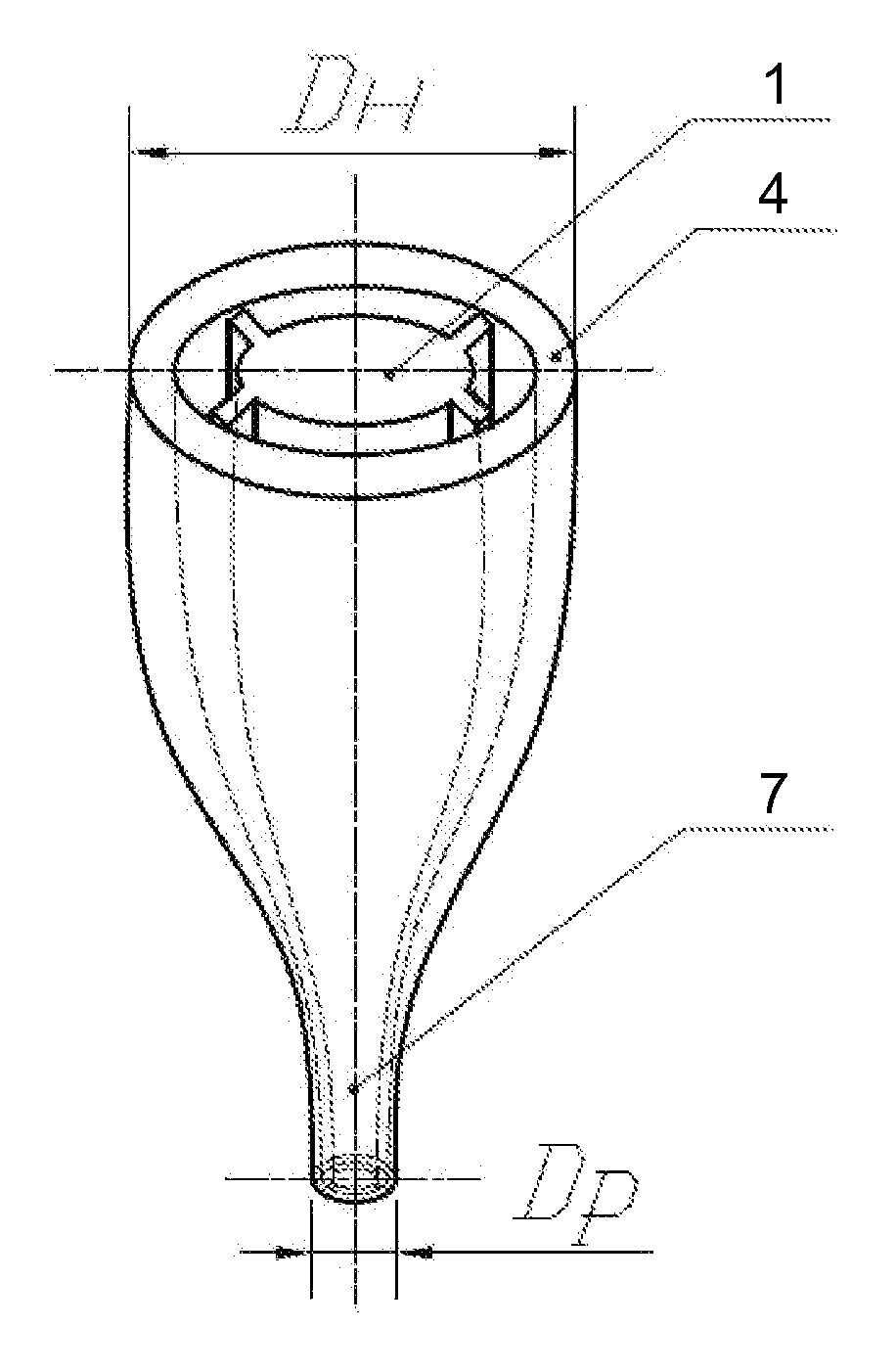
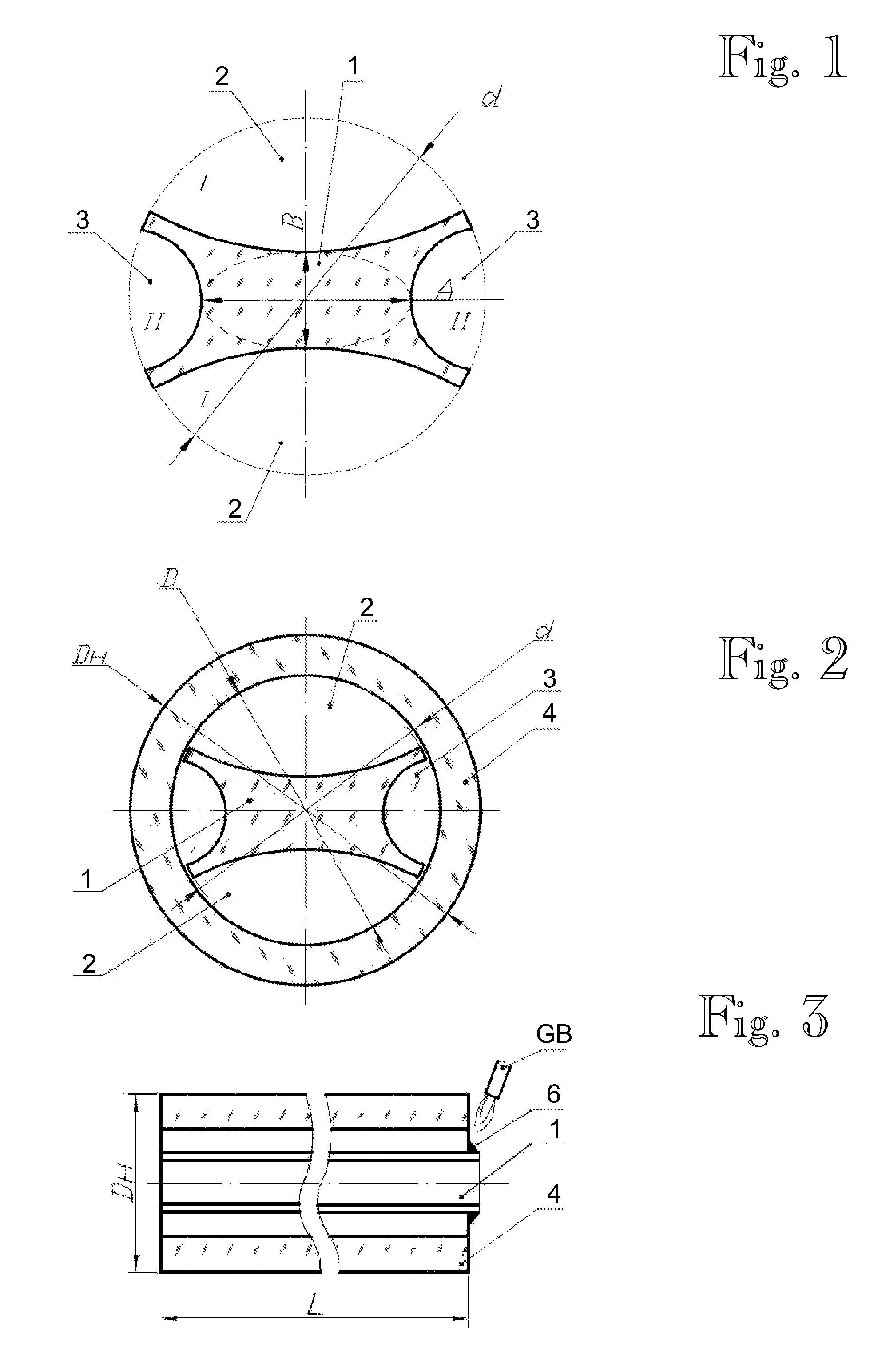
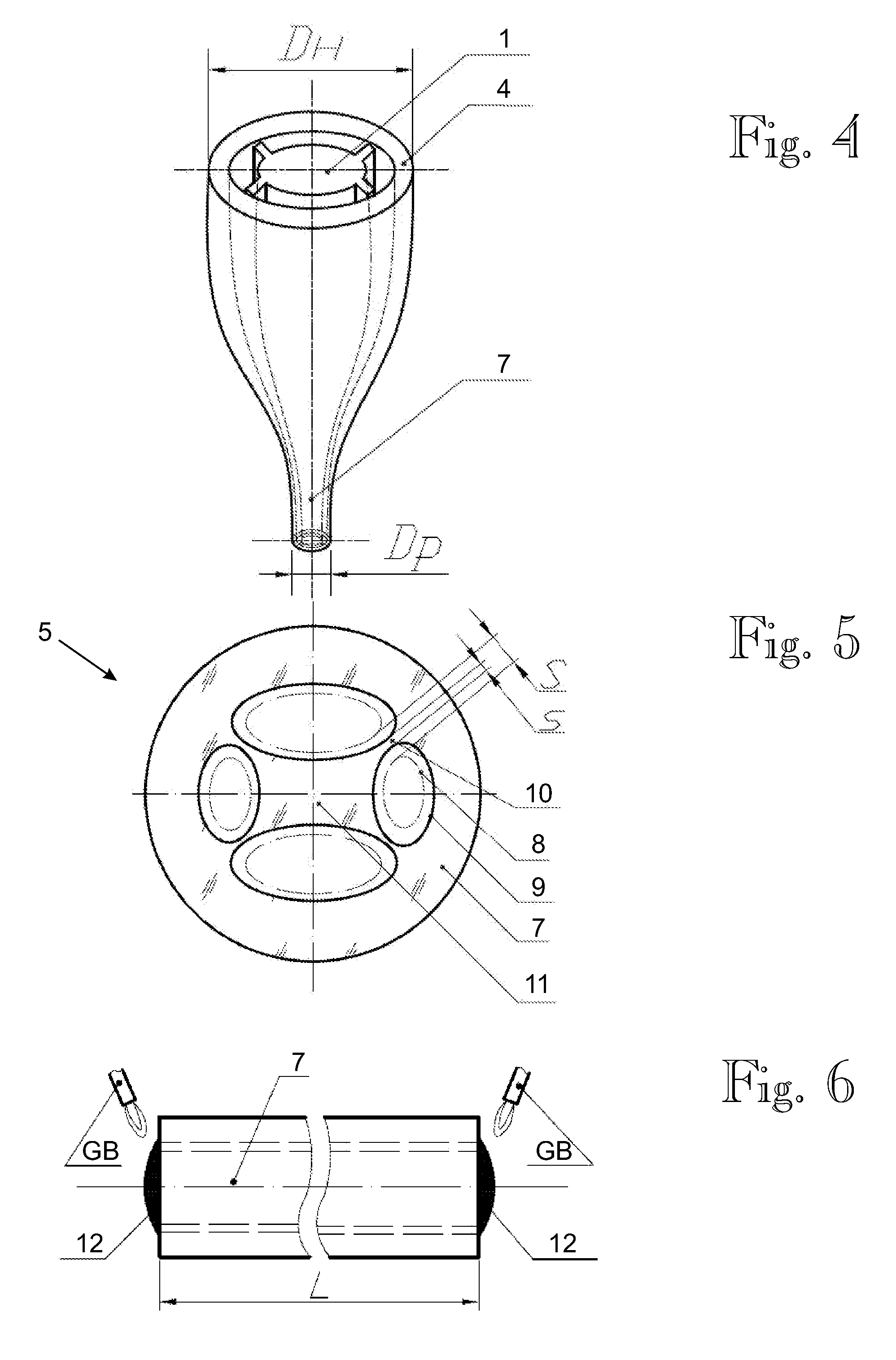
[0055]Reference numerals are assigned as follows in FIGS. 1 through 8: 1—preform rod, 2—first pair of grooves I-I, 3—second pair of grooves II-II, 4—glass (quartz) tube, 5—preform, 6—fusion point, 7—pulled preform, 8—starting channel profile, 9—etched channel profile, 10—channel link struts, 11—preform core area, 12—sealed end of the preform, 13—capillary tube, 14—tubular holder, 15—fusion point of a preform segment 7 and capillary tube 13, 16—gap, 17—protective strengthening coating, 18—MOFSC core area, 19—fiber process matrix area.

[0056]Letter symbols assigned as follows in FIGS. 1 through 8: A—major axis of ellipse of the preform rod in the cross section, B—minor axis of ellipse of the preform rod in the cross section, d—preform rod diameter, D—inner diameter of quartz tube, DH—outer diameter of quartz tube 4, Dp—pulled preform diameter, Dk—outer diameter of quartz capillary tube, dk—inner diameter of quartz capillary tube, L—pre-preform segment length; S—non-etched channel link ...

second embodiment

[0067]FIG. 9 illustrates an embodiment of a manufacturing method for a MOFSC with a high linear birefringence, such as approximately 1*10−2. A starting cylinder-shaped rod 1 with diameter d=19 mm and length L=150-200 mm is made. Three pairs of grooves 2A, 2B and 3 are processed mirror-symmetrically relative to the plane passing through the longitudinal rotation axis of the preform, 5 mm deep semi-circular grooves 3 with a 2 mm radius at the top along one axis, and two pairs of trapezoidal grooves 2A, 2B with an inner base (closer to center) size of 3.5 mm and outer “base” being a partial circle with a length 8.75 mm, and as much as 6.5 mm in depth along the other axes. In this example an irregular groove shape will ensure that the core has the pre-designed size of 9 mm×6 mm and all the link struts 10 have the same thickness, such as 2 mm. The grooves 2A, 2B and 3 on the rod 1 are made, for instance, by grinding on a profile surface grinder with a longitudinal disc movement (relative...

third embodiment

[0069]The third embodiment relates to a method for manufacturing a birefringent microstructured fiber with a moderate ellipticity of the fiber core and a four-groove cladding structure. For example this method is suitable for manufacturing birefringent microstructured fibers with a fiber core whose minor axis is about 80% of the major axis.

[0070]The manufacturing steps of the third embodiment are substantially similar to those of the first embodiment, although the shape of the fiber core differs between the embodiments.

[0071]First, as shown in FIG. 12, a preform rod 1 is provided by grooves by grinding and polishing. The relative dimensions of the core portion of the preform rod determine the ellipticity of the resulting optical fiber. In this particular implementation, the following dimensions were used: d=20 mm, A=12.8 mm, B=10.8 mm, S=3.6 mm. Next, the preform rod is cleaned and dried. Then, as shown in FIG. 13, the preform rod is inserted into an appropriately-sized silica tube ...


PUM

PropertyMeasurementUnit
beating lengthaaaaaaaaaa

Abstract

Method for manufacturing optical fibers, comprising cutting mirror-symmetrical grooves (2, 3) on a preform rod (1) which is inserted into a tube (4) of optical material; fusing the perform rod and the tube in a nonworking area; pulling the fused perform rod and tube into a perform which has longitudinal channels defined by the grooves (2, 3) and the tube (4); cutting the perform (5) into segments; etching the longitudinal channels; sealing segment end(s), assembling segments with a capillary tube and tubular process holder; joining the segment and capillary tube on a side opposite to the tubular process holder; drawing the perform segment into an optical fiber, and applying a protective strengthening coating on the drawn optical fiber. As a result, an optical fiber is produced, which has birefringent properties influenced by dimensions of the mirror-symmetrical grooves and the etching step.

Description

FIELD OF THE INVENTION[0001]The present invention relates generally to the field of fiber optics and particularly to a method for manufacturing a birefringent microstructured optical fibers. To provide some illustrative but non-restrictive examples, such birefringent microstructured optical fibers may be used in sensors for physical quantities, such as electric current, as well as in equipment for processing signals in the optical domain.BACKGROUND OF THE INVENTION[0002]Methods for manufacture of microstructured optical fibers include preform ‘manufacture step and fiber drawing step. Manufacture of preforms involves’ well-known methods including drilling, grinding, polishing, etching and expanding longitudinal channels in preforms, assembly and pulling of quartz preforms made of a set of tubes and rods of various cross-sectional shapes; forming of preform structure by forcing through a mould or die (the method is suitable for light-alloy low melting point materials, for instance, po...

Claims


Application Information

Patent Timeline
Patent Type & Authority Applications(United States)
IPC IPC(8): C03B37/027C03B37/012
CPCC03B37/01208C03B37/01228C03B37/01234C03B37/0124C03B2205/07C03B37/02781C03B2203/20C03B2203/302C03B37/02709C03B37/012C03B37/027G02B6/02
Inventor CHAMOROVSKIY, YURIVOROB' EV, IGORVOLOSHIN, VICTOR
Owner CLOSED PROFOTECH CJSC PROFOTECH
Why Eureka
Try Eureka