Adhesive fastening elements for holding a workpiece and methods of de-bonding a workpiece from an adhesive fastening element

Inactive Publication Date: 2013-01-10
ROLLS ROYCE PLC
View PDF1 Cites 7 Cited by
  • Summary
  • Abstract
  • Description
  • Claims
  • Application Information

AI Technical Summary

Benefits of technology

[0072]The light source may be turned off when the light meter detects that the adhesive is cured. This ma

Problems solved by technology

The most common methods of workholding, i.e. mechanical clamping, vacuumed chucks and magnetic systems, all possess some limitations, particularly when delicate or difficult to hold parts require processing which involves mechanical loading (e.g. machining).
However, encapsulation is often undesirable as the parts have to be subsequently removed from the encapsulation media.
Furthermore, whilst low melt alloys such as lead-bismuth-tin composition are stronger than waxes, small amounts of the alloy may be left on the workpiece (i.e. a turbine blade), causing corrosion problems.
However, such systems are complex and thus expensive.
The components are also susceptible to gradual movement if a continuous force is applied.
However, it is necessary to de-bond the workpiece from the workholding device after the machining operation has been completed.
This may not always be possible with fragile components.
Furthermore, the translation of the gripping pin 3 may cause damage to the workpiece 5 even when supported by the annular shoulder 19.
As described above, mechanically breaking the bond can induce large stresses in the workpiece and is therefore unsuitable for fragile items.
Furthermore, depending on the geomet

Method used


Image

  • Adhesive fastening elements for holding a workpiece and methods of de-bonding a workpiece from an adhesive fastening element
  • Adhesive fastening elements for holding a workpiece and methods of de-bonding a workpiece from an adhesive fastening element
  • Adhesive fastening elements for holding a workpiece and methods of de-bonding a workpiece from an adhesive fastening element

Examples


Embodiment Construction

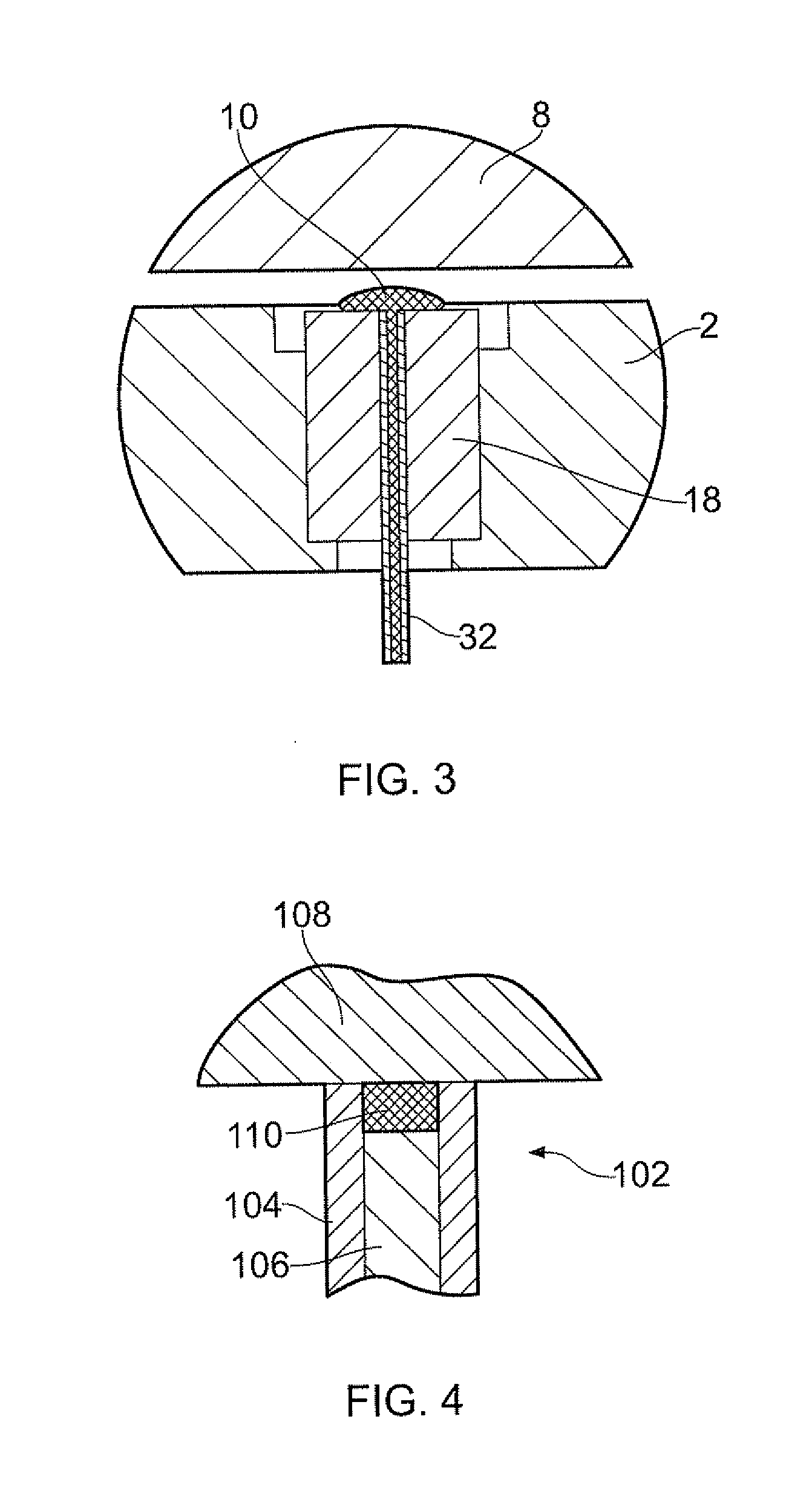
[0155]With reference to FIG. 3, an embodiment of an adhesive fastening element 2 in accordance with an aspect of the invention is shown. The adhesive fastening element 2 comprises a core formed from an optical material 18. An adhesive delivery tube 32 is embedded in the adhesive fastening element 2 and extends through the optical material 18. The adhesive delivery tube 32 provides a conduit for supplying a photo-activated adhesive 10 to an exterior surface of the adhesive fastening element 2 where it may be used to bond a workpiece 8 to the adhesive fastening element 2.

[0156]The adhesive 10 is pumped through the adhesive delivery tube 32 using a suitable pumping means (not shown). Once a sufficient amount of adhesive has been supplied to the surface of the adhesive fastening element 2, a bond may be formed between the adhesive fastening element 2 and the workpiece 8 by supplying light to the adhesive 10 through the optical material 18 to cure the photo-activated adhesive 10. In this...


PUM


Abstract

An adhesive fastening element (602) for holding a workpiece (608), the adhesive fastening element (602) comprising: a body (604, 606) defining a recess (642) for receiving a protrusion (644) of the workpiece (608); wherein, in use, adhesive is applied between an end surface of the recess (642) and an end surface of the protrusion (644) and between a side surface of the recess (642) and a side surface of the protrusion (644) to bond the workpiece (608) to the adhesive fastening element (602). The workpiece (608) may be aligned with a reference point on the adhesive fastening element (602) and the adhesive cured to fix the position of the workpiece (608) relative to the adhesive fastening element (602).

Description

[0001]The present invention relates to adhesive fastening elements for holding a workpiece and methods of de-bonding a workpiece from an adhesive fastening element.BACKGROUND[0002]It is known to use workholding devices to hold a workpiece still whilst performing manufacturing processes, such as machining, or whilst inspecting the workpiece.[0003]The most common methods of workholding, i.e. mechanical clamping, vacuumed chucks and magnetic systems, all possess some limitations, particularly when delicate or difficult to hold parts require processing which involves mechanical loading (e.g. machining).[0004]Several non-conventional workholding technologies have been developed to address some of the limitations of the common methods described above.[0005]For example, low melt alloys, adhesives, resins, waxes, and water-ice have been employed to encapsulate irregular or delicate parts in order to ease manufacture. However, encapsulation is often undesirable as the parts have to be subseq...

Claims


Application Information

Patent Timeline
IPC IPC(8): F16B47/00F16B35/00B32B37/12
CPCB23Q3/084Y10T24/33Y10T156/11
Inventor RAFFLES, MARK H.LLEWELLYN-POWELL, HELEN L.HIGH, COLIN J.
Owner ROLLS ROYCE PLC
Why Eureka
Try Eureka