Synthesis gas method and apparatus

a synthesis gas and gas technology, applied in the direction of products, organic chemistry, oxygen/ozone/oxide/hydroxide, etc., can solve the problems of degrading the reform catalyst used in connection, the conventional method of producing a synthesis gas such as the one discussed above, and the production of synthesis gas is not optimal, so as to reduce the slip of methane and increase the equilibrium temperature

Inactive Publication Date: 2013-01-10
PRAXAIR TECH INC
View PDF0 Cites 34 Cited by
  • Summary
  • Abstract
  • Description
  • Claims
  • Application Information

AI Technical Summary

Benefits of technology

[0010]The present invention provides, in one aspect, a method for producing a synthesis gas product. In accordance with such method, permeate and retentate sides of at least one oxygen transport membrane element, configured to separate oxygen through oxygen ion transport, are contacted with a hydrogen containing stream formed from a synthesis gas containing no more than 20 percent methane by volume, hydrogen and an oxygen containing stream, respectively. The hydrogen containing stream is reacted with the oxygen transported through the at least one oxygen transport membrane element, thereby generating heat, a heated reaction product stream, and a heated retentate stream. The heated reaction product stream is combined with a reactant stream to form a combined stream comprising hydrocarbons contributed by the reactant stream and steam contributed at least by the heated reaction product stream. The hydrocarbons and steam contained in the combined stream are reacted in at least one catalytic reactor to produce a synthesis gas stream. Heat generated by the at least one oxygen transport membrane element to the at least one catalytic reactor by radiation from the at least one oxygen transport membrane element and by indirect heat transfer from the heated retentate stream to the at least one catalytic reactor to assist in supporting endothermic heating requirements of the steam methane reforming reaction. The synthesis gas product is produced from at least part of the synthesis gas stream.
[0011]Unlike the prior art, the oxygen transport membrane is used to generate heat and potentially steam for the steam methane reforming and such heat is transferred to a separate catalytic reactor. A major advantage in such an arrangement is that the combustion of synthesis gas with permeated oxygen is a far more rapid reaction than methane or methane and higher order hydrocarbons. In the prior art, generally a pre-reformed stream that would be mostly methane and steam is combusted at the permeate side of an oxygen transport membrane that also contains a catalyst to promote steam methane reforming reactions. Consequently, a reactive system in accordance with the present invention may use far less oxygen transport membrane area than a prior art reactor. This translates into a reactive system in accordance with the present invention that is less complex and expensive than prior art systems and further, is less susceptible to failure. Additionally, since the catalytic reactor is a separate unit, the catalyst can more easily be replaced than in a prior art system in which the catalyst is incorporated into an oxygen transport membrane element.
[0013]A supplementary steam stream can be introduced into at least one of the hydrogen containing stream and the reactant stream. The at least one catalytic reactor can have a polishing section heated by an auxiliary burner fired by a fuel thereby increasing the equilibrium temperature at the outlet of the at least one catalytic reactor and reducing methane slip from such reactor or reactors. The heated retentate supports combustion of the fuel within the auxiliary burner prior to preheating the oxygen containing stream.
[0017]The at least one catalytic reactor is configured to react the hydrocarbons and steam to produce a synthesis gas stream and thereby to, at least in part, produce the synthesis gas product. The at least one catalytic reactor is connected to the at least one oxygen transport membrane element such that the heated reaction product stream is combined with a reactant stream containing the hydrocarbons to form a combined stream comprising the hydrocarbons contributed by the reactant stream and steam contributed at least by the heated reaction product stream that is introduced into the at least one catalytic reactor. The at least one oxygen transport membrane element and the at least one catalytic reactor are positioned with respect to one another within an elongated insulated housing such that the heat is radiated from the at least one oxygen transport membrane element to the at least one catalytic reactor and is indirectly transferred from the heated retentate stream to the at least one catalytic reactor to assist in supporting endothermic heating requirements of the steam methane reforming reaction.
[0020]A heat exchanger can be connected to the oxygen separation device and configured such that the oxygen containing stream is preheated through indirect heat exchange with the heated retentate stream prior to being introduced to the retentate side of the at least one oxygen transport membrane element. The at least one catalytic reactor can have a polishing section situated within a duct that contains a burner fired by a fuel thereby increasing the equilibrium temperature at the outlet of the at least one catalytic reactor and reducing methane slip from such reactor or reactors. The duct burner is positioned between the oxygen separation device and the heat exchanger such that the heated retentate supports combustion of the fuel within the duct burner prior to preheating the oxygen containing stream within the heat exchanger.
[0021]In a specific embodiment of the present invention, the at least one catalytic reactor is at least one first catalytic reactor and at least one second catalytic reactor is provided that is configured to react additional hydrocarbons contained in a subsidiary reactant stream with further steam, thereby producing a subsidiary synthesis gas stream. The permeate side of the at least one oxygen transport membrane element is connected to the at least one second catalytic reactor such that the hydrogen containing stream is formed, at least in part, from the subsidiary synthesis gas stream. The at least one second catalytic reactor is positioned such that heat generated by the at least one oxygen transport membrane element is also transferred by radiation and through indirect heat transfer from the heated retentate stream to the at least one second catalytic reactor to assist in supporting endothermic heating requirements of the steam methane reforming reaction.

Problems solved by technology

This is not optimal for the production of synthesis gas for synthetic fuel production such as in Fisher-Tropsch or methanol synthesis where a hydrogen to carbon monoxide ratio of 1.8 to 2.0 within the synthesis gas is more desirable.
As can be appreciated, conventional methods of producing a synthesis gas such as have been discussed above are expensive and complex installations.
Such carbon deposition will degrade reforming catalyst used in connection with the oxygen transport membrane reactor.
The problem with all of these systems is that an oxygen transport membrane will operate at high temperatures of about 900° C. to 1100° C. Where hydrocarbons such as methane and also higher order hydrocarbons are subjected to such temperatures carbon formation will occur.
As such, the oxygen is not generally available at the entrance to the reactor.
This also results in an aggravated carbon formation problem at the entrance that is especially the case at low steam-to-carbon ratios.
In any case, a reactant containing methane and steam will produce a relatively low oxygen flux across the membrane resulting in the membrane area required for such a reactor to be larger and it will add to the expense and complexity in such a reactor.
In prior art reactor designs where the catalyst is employed adjacent to the oxygen transport membrane, catalyst replacement becomes an expensive if not impractical exercise.

Method used


Image

  • Synthesis gas method and apparatus
  • Synthesis gas method and apparatus
  • Synthesis gas method and apparatus

Examples


Embodiment Construction

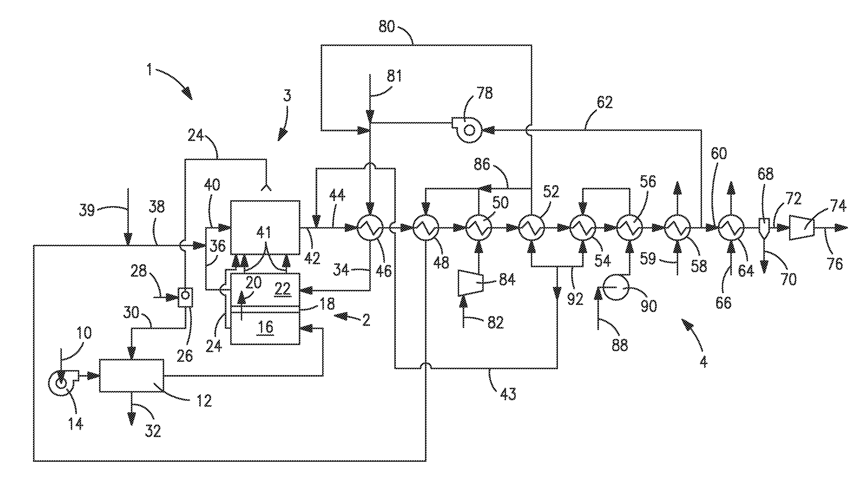
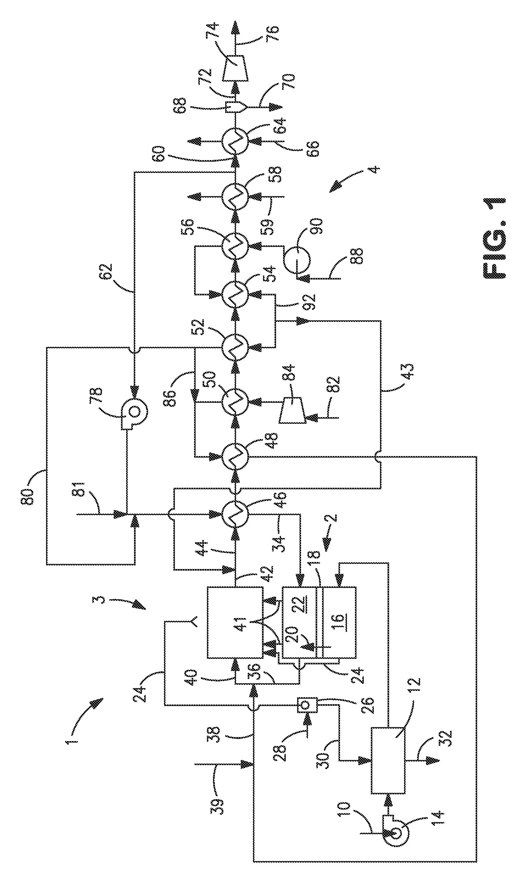
[0040]With reference to FIG. 1, an apparatus 1 is illustrated that is designed to produce a synthesis gas product through the steam methane reforming of hydrocarbons. Apparatus 1 includes one or more oxygen transport membrane elements of which oxygen transport membrane element 2 is illustrated. Oxygen transport membrane element 2 supplies heat by radiation and convective heat transfer to supply the endothermic heating requirements of a catalytic reactor 3 within which the hydrocarbons and steam are reacted to produce a synthesis gas. As well known in the art, at high temperatures, from 700 to 1100° C., steam will react with methane to yield a synthesis gas that contains hydrogen and carbon monoxide. Catalytic reactor 3, as would be known in the art, contains a catalyst, typically nickel, to promote such steam methane reforming reaction. Additionally, water-gas shift reactions occur in which the carbon monoxide will react with the steam to produce carbon dioxide and hydrogen. Althoug...


PUM

PropertyMeasurementUnit
temperaturesaaaaaaaaaa
pore diameteraaaaaaaaaa

Abstract

A method and apparatus for producing a synthesis gas product having one or more oxygen transport membrane elements thermally coupled to one or more catalytic reactors such that heat generated from the oxygen transport membrane element supplies endothermic heating requirements for steam methane reforming reactions occurring within the catalytic reactor through radiation and convention heat transfer. A hydrogen containing stream containing no more than 20 percent methane is combusted within the oxygen transport membrane element to produce the heat and a heated combustion product stream. The heated combustion product stream is combined with a reactant stream to form a combined stream that is subjected to the reforming within the catalytic reactor. The apparatus may include modules in which tubular membrane elements surround a central reactor tube.

Description

FIELD OF THE INVENTION[0001]The present invention provides a method and apparatus for producing a synthesis gas product in which a hydrogen containing stream composed of a synthesis gas containing no more than 20 percent by volume methane is reacted with oxygen permeating through an oxygen transport membrane to generate heat to heat the membrane and support endothermic heating requirements of steam methane reforming reactions conducted in a separate catalytic reactor designed to produce the synthesis gas product.BACKGROUND OF THE INVENTION[0002]Synthesis gas containing hydrogen and carbon monoxide is produced for a variety of industrial applications, for example, the production of hydrogen, chemicals and synthetic fuel production. Conventionally, the synthesis gas is produced in a fired reformer in which natural gas and steam is reformed to the synthesis gas in catalyst filled reformer tubes. The endothermic heating requirements for steam methane reforming reactions occurring within...

Claims


Application Information

Patent Timeline
Patent Type & Authority Applications(United States)
IPC IPC(8): C01B3/38B01J10/00
CPCC01B3/384B01J8/00C01B2203/0233C01B2203/0238C01B2203/062C01B2203/0822C01B2203/0827C01B2203/0883C01B2203/1058C01B2203/1241B01J19/2475B01J19/2485B01J8/0285B01J2208/00309B01J2208/00504B01J2208/00902B01J2219/00117B01J2219/00157C01B13/0251Y02P20/10Y02P20/141
Inventor KELLY, SEAN M.KROMER, BRIAN R.LITWIN, MICHAEL M.ROSEN, LEE J.CHRISTIE, GERVASE MAXWELLWILSON, JAMIE R.KOSOWSKI, LAWRENCE W.ROBINSON, CHARLES
Owner PRAXAIR TECH INC
Why Eureka
Try Eureka