Power generator module connectivity control

a power generator and module technology, applied in photovoltaic monitoring, dc source parallel operation, two-wire dc circuits, etc., can solve problems such as danger to emergency personnel such as firemen and pv system maintenance personnel, and excessive reverse currents from other strings

Inactive Publication Date: 2013-01-10
SENSATA TECHNOLOGIES INC
View PDF10 Cites 65 Cited by
  • Summary
  • Abstract
  • Description
  • Claims
  • Application Information

AI Technical Summary

Benefits of technology

[0127]Control circuit 1410 provides flexibility to predetermine terminal voltage thresholds to close and open switch 1450. The control circuit 1410 latches the relay closed and open. If the output terminals become electrically separated from an external power source or load, the state of switch 1450 does not change because it is latched.
[0128]For example, as shown, the electromechanical relay version of said apparatus with a normally-open relay switch 1450 replacing the FET as previously discussed. Transistor T3 drives relay coil. Diode D6 prevents excessive voltage from appearing across T3, and diode D5 along with the PV panel prevents excessive voltage from appearing across positive and negative output terminals.

Problems solved by technology

In certain cases, faults in a string can cause excessive reverse currents from other strings.
However, disconnection and reconnection of the photovoltaic power near the load 110 does not ensure that both the current and the voltage levels are safe between the PV module system and the DC switch 120, thereby representing a potential danger to emergency personnel such as firemen and PV system maintenance personnel.

Method used


Image

  • Power generator module connectivity control
  • Power generator module connectivity control
  • Power generator module connectivity control

Examples


Embodiment Construction

[0030]As discussed above, embodiments herein deviate with respect to conventional power generation systems.

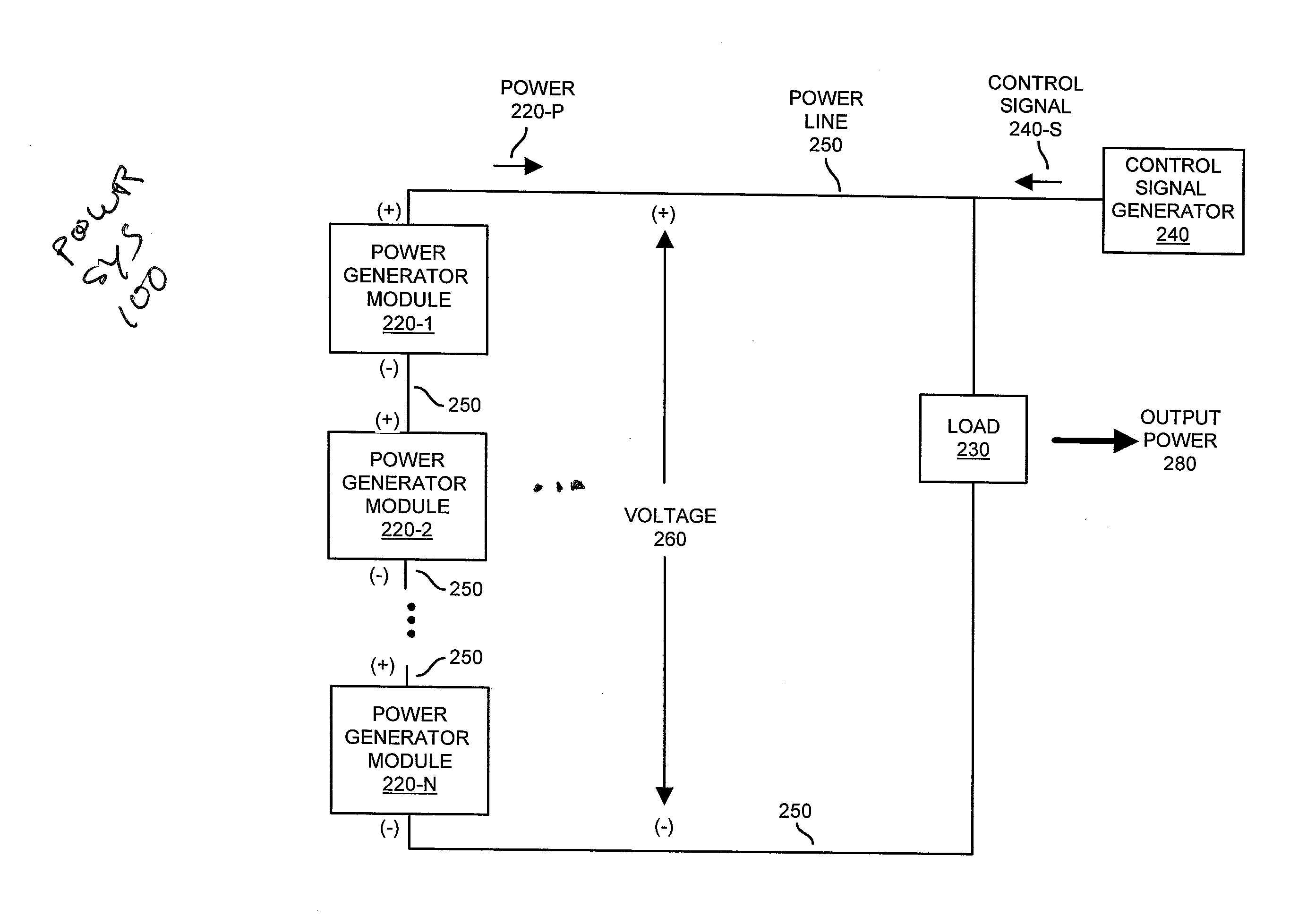
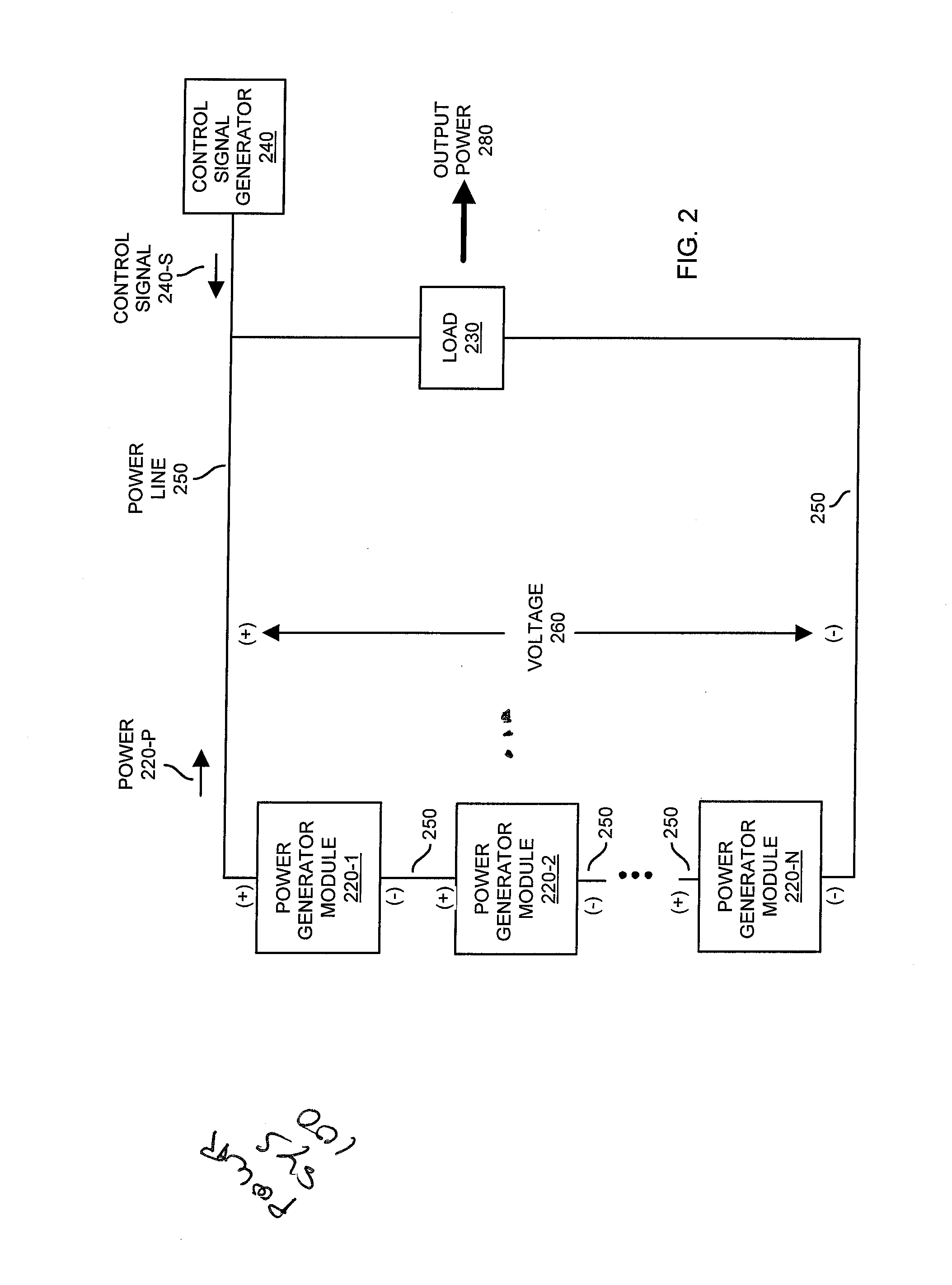
[0031]More specifically, FIG. 2 is an example diagram illustrating control of a series connection of selectively activated power generator modules according to embodiments herein.

[0032]As shown, power system 100 includes at least one string of power generator modules 220 (e.g., power generator module 220-1, power generator module 220-2, . . . , power generator module 220-N), control signal generator 240, and load 230.

[0033]Note that the power system 100 can include any suitable number of strings of power generator modules 220 in parallel to produce voltage 260.

[0034]As its name suggests, control signal generator 240 generates one or more control signals 240-S to control the power generator modules 220.

[0035]More specifically, in one embodiment, control signal generator 240 produces control signal 240-S to control functionality associated with the power generator modules 220. Fo...


PUM


Abstract

A remote resource can be configured to control connectivity of the power generator modules in a string. For example, a respective power generator module can include a current sense circuit that monitors for presence of communication signal. The power generator module can monitor for a presence of a remotely generated control signal over power line that is used by the respective power generator module to convey power to the external load. If the control signal is present on the power line, as generated by the remote resource, the control circuit in the respective power generator module activates the switch to an ON state such that respective activated power generator module is connected in series with the other activated power generator modules. If no keep-alive control signal is detected within a timeout period, the controller deactivates the respective power generator module.

Description

RELATED APPLICATIONS[0001]This application is related to and claims the benefit of earlier filed U.S. Provisional Patent Application Ser. No. 61 / 491,359 entitled “Photovoltaic Module Latch,” filed on May 31, 2011, the entire teachings of which are incorporated herein by this reference.[0002]This application is also related to and claims the benefit of earlier filed U.S. Provisional Patent Application Ser. No. 61 / 579,437 entitled “Photovoltaic Module Level Disconnect,” filed on Dec. 22, 2011, the entire teachings of which are incorporated herein by this reference.BACKGROUND[0003]Conventional PhotoVoltaic (PV) power systems produce power for many types of applications. For example, in one conventional application, the power generated by a solar array can be used to charge batteries that make power available during non-daylight hours.[0004]FIG. 1 is a diagram illustrating a typical PV array 105 (e.g., multiple PV devices 135 connected in series) driving inverter or charger load 110. Ea...

Claims


Application Information

Patent Timeline
Patent Type & Authority Applications(United States)
IPC IPC(8): H02J1/06
CPCH02J3/383H02J13/0003H02H7/20H02J7/35Y02E40/72Y02E10/566Y04S10/123H01L31/02021H02S50/10Y02E10/563H02J2300/24H02J3/381H02J13/0004Y02E10/56Y02E40/70H02J1/10H02J13/00002Y04S10/30Y02E60/00
Inventor KAWATE, KEITH W.PINETTE, CHRISTOPHER E.WEZOWICZ, JOHN R.MAHER, THOMAS R.ROSE, MICHAEL B.
Owner SENSATA TECHNOLOGIES INC
Why Eureka
Try Eureka