Method and device of differential confocal and interference measurement for multiple parameters of an element

a technology of interference measurement and multiple parameters, applied in the field of optical precision measurement technology, can solve the problems of affecting the imaging quality of the system, the increase in system aberration, and the largely affected measurement accuracy of the system, so as to improve the focusing precision of the target, improve the measurement efficiency, and improve the measurement method. the effect of simple and easy operation

Inactive Publication Date: 2013-01-10
BEIJING INSTITUTE OF TECHNOLOGYGY
View PDF7 Cites 29 Cited by
  • Summary
  • Abstract
  • Description
  • Claims
  • Application Information

AI Technical Summary

Benefits of technology

[0024]1) Surface profile interference technology and differential confocal (confocal) focusing technology are combined. The surface profile of an element is measured by using a figure interference measuring system, and the surface curvature radius of an element with spherical surface, the back focal length of a lens, the refractive index of a lens, the thickness of a lens and the axial spaces of an assembled lenses are measured by using a differential confocal (confocal) measuring system, thus concurrent measurement of multiple parameters of an element can be realized, and the measuring efficiency can be improved.
[0025]2) Surface prof

Problems solved by technology

For example, for the object lenses of a lithography machine, the deviation of the surface curvature radius, of the center thickness and of the material refractive index and the decrease of the accuracy of the surface profile of each lens will cause the increase in the aberration of the system, thereby affecting the imaging quality of the system.
However, spherical template method is only suitable for measuring a small curvature radius and its measurement accuracy will be largely affected by the surface profile of the template.
During contact measurement, there exists a measurement error resulted from the wearing and pressing of spherical surface.
Autocollimation method belongs to non-contact measurement, but component polishing is needed, in which the adjustment of optical paths is complex, and it is difficult for focusing and aligning, thus system error may be caused during measuring.
Interferometer method, during measuring, may be interfered by factors such as temperature, air flow, vibration and noise, etc., thus the measurement accuracy will be largely affected.
The measurement accuracy obtained with this method is somewhat higher than that obtained with traditional lens imaging measuring method, but it has a defect that the preparation process of the refractive index liquid is boresome and the thickness needs to be measured separately, thus an auxiliary measuring apparatus is needed and it is difficult to realize engineering.
However it has a defect that the data processing procedure is boresome and the measurement accuracy is not high because interference imagin

Method used


Image

  • Method and device of differential confocal and interference measurement for multiple parameters of an element
  • Method and device of differential confocal and interference measurement for multiple parameters of an element
  • Method and device of differential confocal and interference measurement for multiple parameters of an element

Examples


embodiment 1

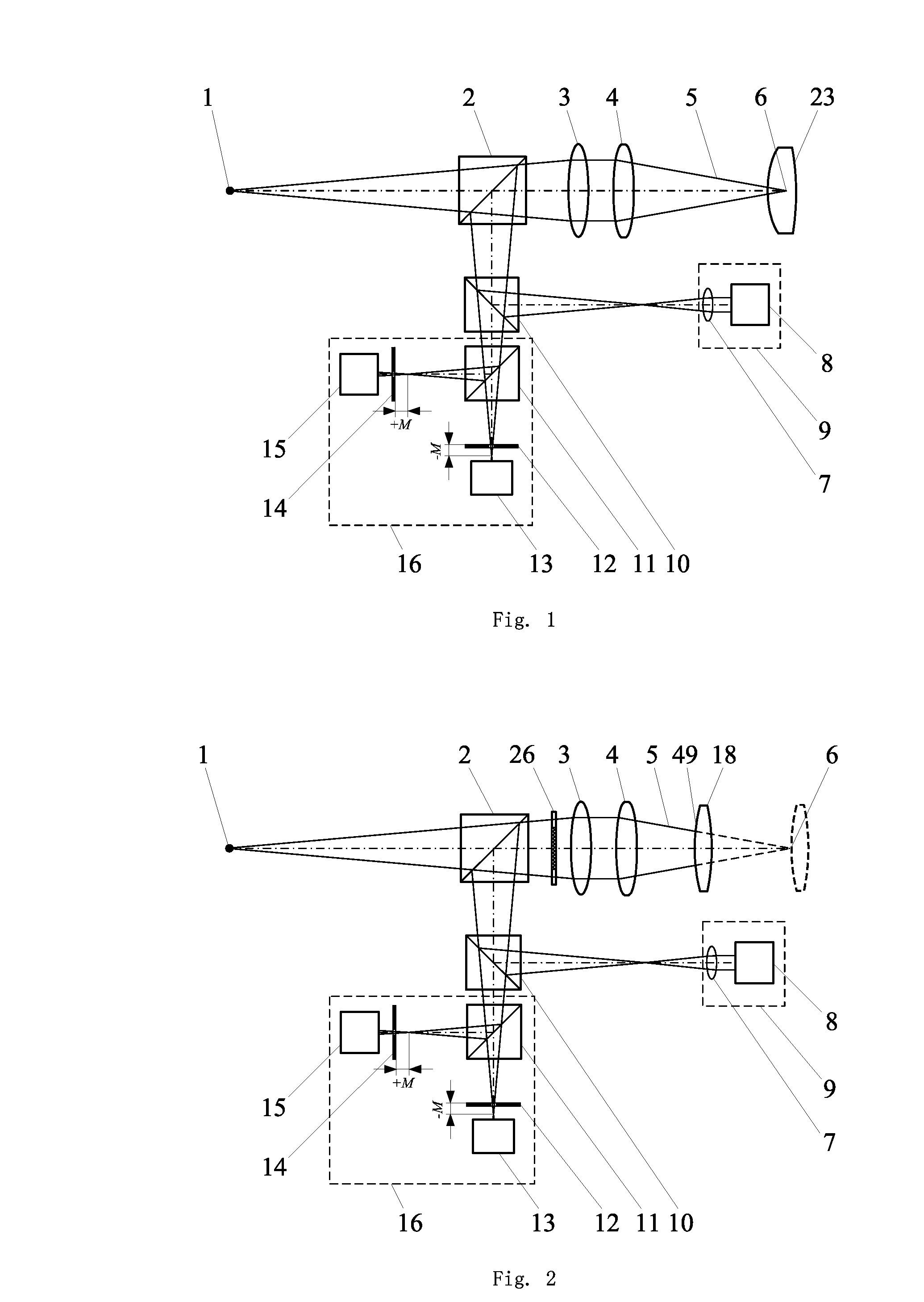
[0047]When the curvature radius of a convex spherical surface is measured by a device of differential confocal and interference measurement for multiple parameters of an element, the device of differential confocal and interference measurement for multiple parameters of an element is as shown in FIG. 9 the measuring steps are as follows:

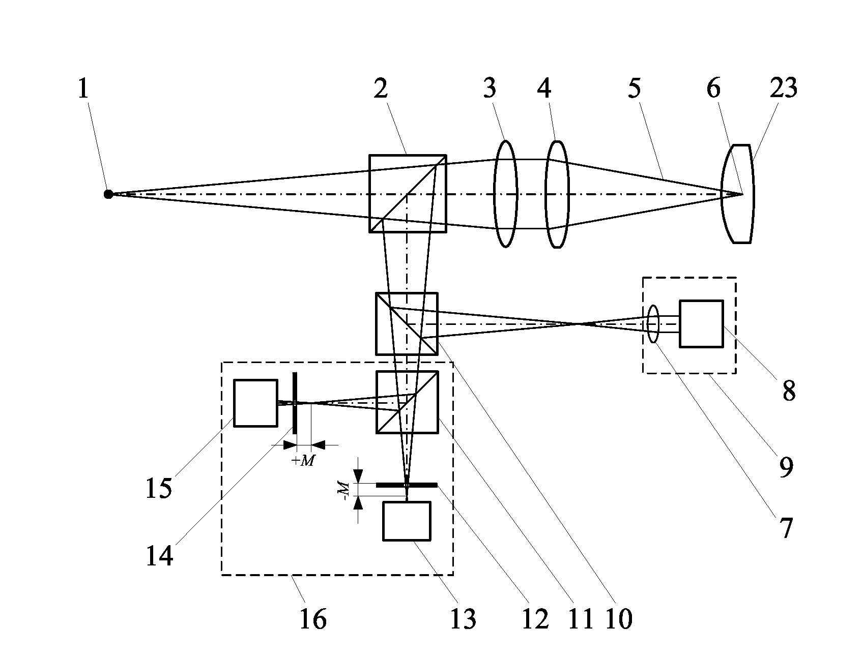
[0048]a) starting up a measurement software in a master control computer 32, and turning on a laser 37, wherein the light emitted by the laser 37 forms a point light source 1 after being transmitted via an optical fiber 38, and the light emitted from the point light source 1 forms a measurement beam 5 after passing through a first beam splitter 2, a collimating lens 3 and a converging lens 4;

[0049]b) fixing a test element with spherical surface 18 on a 5 dimensional (5D) adjusting mount 39; irradiating the measurement beam 5 on a surface of the test element with spherical surface 49, and passing the light reflected by the surface 49 of the element wi...

embodiment 2

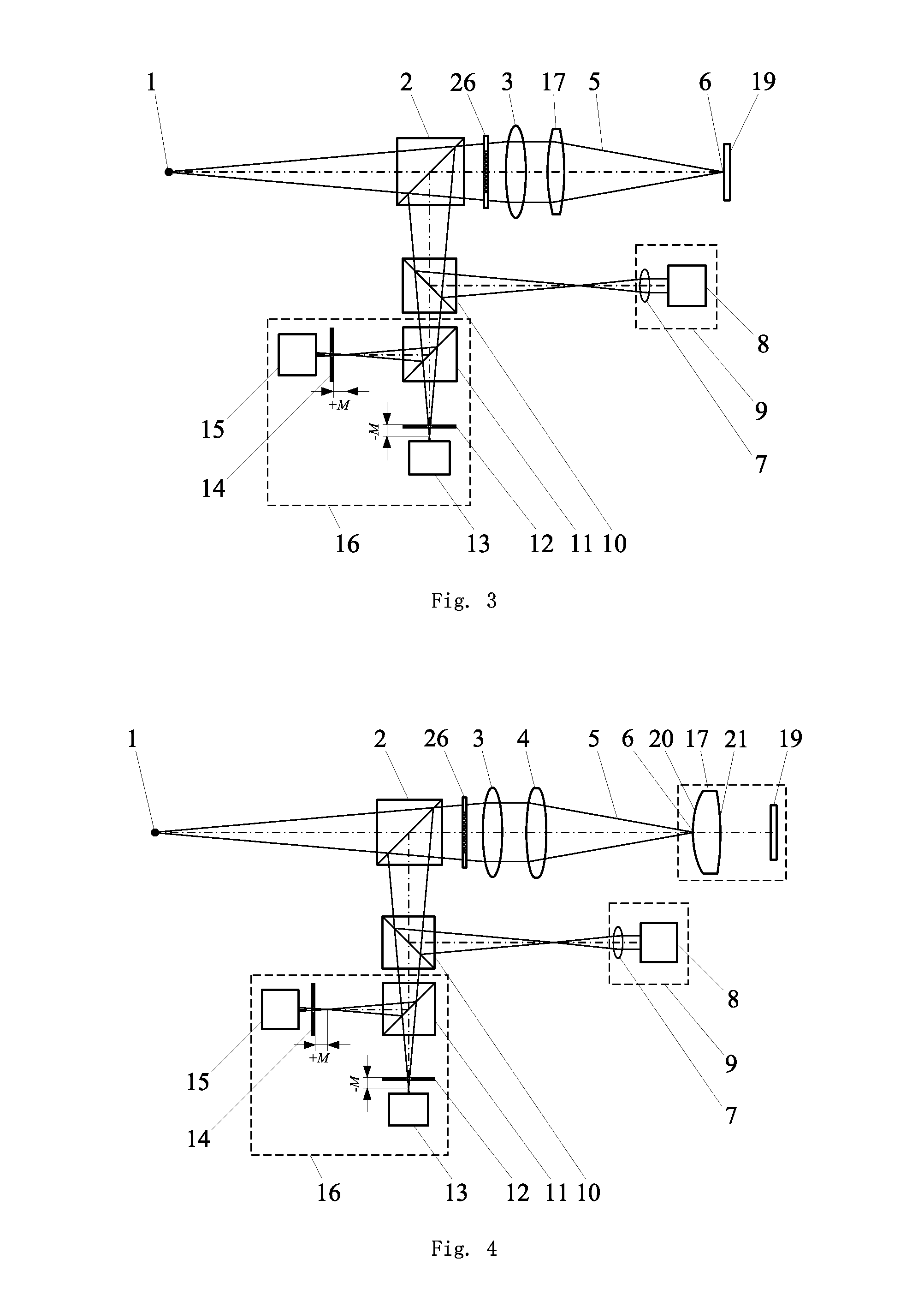
[0058]When the back focal length of a convex lens is measured by a device of differential confocal and interference measurement for multiple parameters of an element, as shown in FIG. 10, the measuring steps of the device of differential confocal and interference measurement for multiple parameters of an element are as follows:

[0059]a) starting up a measurement software in a master control computer, and turning on a laser 37, wherein the light emitted by the laser 37 forms a point light source 1 after being transmitted via an optical fiber 38, and the light emitted from the point light source 1 passes through a first beam splitter 2 and a collimating lens 3 to form a parallel light beam;

[0060]b) removing the converging lens 4, and placing a test lens 17 on the optical path of the parallel light emitted from the collimating lens 3, and adjusting the test lens 17 such that it is co-optical-axial with the collimating lens 3, and then passing the parallel light through the test lens 17 ...

embodiment 3

[0067]When the refractive index and the thickness of K9 plano-convex lens is measured by a device of differential confocal and interference measurement for multiple parameters of an element, as shown in FIG. 11, the measuring steps of the device of differential confocal and interference measurement for multiple parameters of an element are as follows:

[0068]a) starting up a measurement software in a master control computer 32, and turning on a laser 37, wherein the light emitted by the laser 37 forms a point light source 1 after being transmitted via an optical fiber 38, and the light emitted from the point light source 1 forms a measurement beam 5 after passing through a first beam splitter 2, a collimating lens 3 and a converging lens 4;

[0069]b) fixing a test lens 17 on a 5D adjusting mount 39, and fixing a reflector 19 behind the test lens 17, adjusting the test lens 17 such that it is co-optical-axial with the measurement beam 5, and adjusting the reflector 19 such that it is per...


PUM


Abstract

The present invention relates to the field of optical precision measurement technologies, and in particular, to a method and a device of differential confocal (confocal) and interference measurement for multiple parameters of an element. The core concept of the invention lies in that: the concurrent high-precision measurement of multiple parameters of an element may be realized by measuring the surface curvature radius of an element with spherical surface, the back focal length of a lens, the refractive index of a lens, the thickness of a lens and the axial spaces of an assembled lenses by using a differential confocal (confocal) measuring system and measuring the surface profile of the element by using a figure interference measuring system. In the invention, a differential confocal (confocal) detection system and a figure interference measuring system are combined for the first time, the method covers more measured parameters, and during the measurement of multiple parameters of an element, it is not essential to readjust the optical path or disassemble the test element, thus no damage will be caused on the test element, and the measurement speed will be fast.

Description

FIELD OF THE INVENTION[0001]The present invention relates to the field of optical precision measurement technology, which can be applied to measure multiple parameters and the surface profile of an element with high precision.BACKGROUND OF THE INVENTION[0002]In the field of optical precision measurements, it has important meanings to measure various parameters of an element with high precision. There are many kinds of element parameters, for example, the surface curvature radius of an element with spherical surface, the refractive index of a lens, the center thickness of a lens, the axial spaces of an assembled lenses and the surface profile of an element, etc. These parameters are very important in the manufacturing process of an optical element, and the processing accuracy will have a significant effect on the imaging quality of an optical system. Especially, in high-performance optical systems such as object lenses of a lithography machine and lens of an astronautic camera, etc.,...

Claims


Application Information

Patent Timeline
IPC IPC(8): G01B11/24G01N21/41G01B11/06G01B11/255G01B11/02
CPCG01B11/06G01B11/14G01M11/0271G01B11/255G01M11/025G01B11/2441
Inventor ZHAO, WEIQIANYANG, JIAMIAOQIU, LIRONGWANG, YUNLI, JIA
Owner BEIJING INSTITUTE OF TECHNOLOGYGY
Why Eureka
Try Eureka