Q-switching-induced Gain-switched Erbium Pulse Laser System

a pulse laser and erbium pulse technology, applied in electromagnetic transmission, transmission, active medium materials, etc., can solve the problems of large volume, difficult optical alignment, high cavity loss, etc., and achieve high laser efficiency

Inactive Publication Date: 2013-01-17
NAT CHENG KUNG UNIV
View PDF12 Cites 19 Cited by
  • Summary
  • Abstract
  • Description
  • Claims
  • Application Information

AI Technical Summary

Benefits of technology

[0011]It is another object of the present invention to provide an all-fiber Q-switching-induced gain-switched erbium pulse laser system, capable of generating erbium laser pulses within the 2.5 μm to 3.0 μm wavelength region, by means of a Q-switch component, and capable of achieving higher laser efficiency in an all-fiber laser scheme.
[0028]Thereby, the all-fiber Q-switching-induced gain-switched erbium pulse laser system of the present invention may use the saturable absorber Q-switch fiber to induce an operation of gain-switching, so that a laser pulse within the 2.5 to 3.0 μm wavelength region is formed from the Er3+-doped gain fiber, in an all-fiber laser scheme with high laser efficiency.

Problems solved by technology

However, the conventional laser system that employs the active bulk Q-switches has disadvantages of large volume, difficulty of optical alignment and high cavity loss.

Method used


Image

  • Q-switching-induced Gain-switched Erbium Pulse Laser System
  • Q-switching-induced Gain-switched Erbium Pulse Laser System
  • Q-switching-induced Gain-switched Erbium Pulse Laser System

Examples


preparation 1

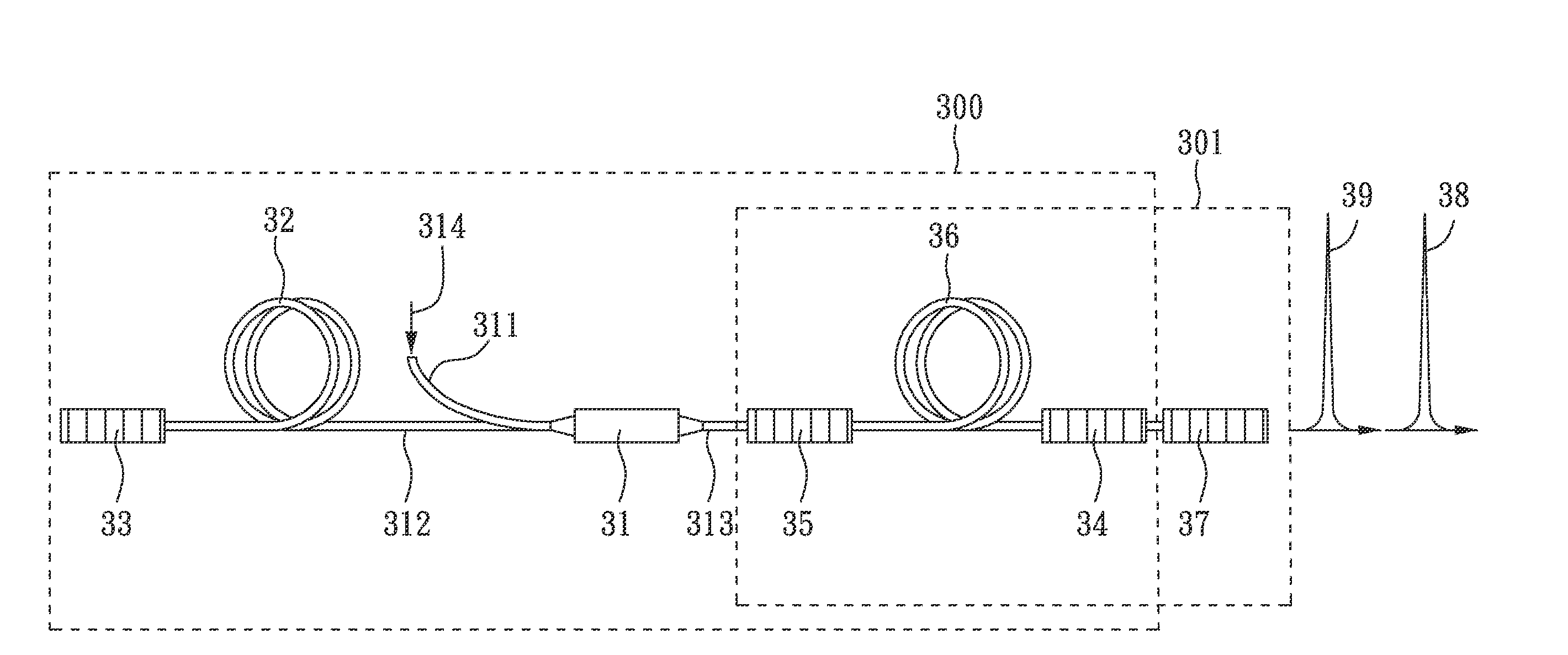
[0033]Please refer to FIG. 1, which is a schematic diagram of the Q-switching-induced gain-switched erbium pulse laser system according to the first embodiment of the present invention. As shown FIG. 1, the Q-switching-induced gain-switched erbium pulse laser system according to the first embodiment of the present invention includes: a first laser resonator 11, a second laser resonator 12 and a pumping light source component 13. The first laser resonator 11 comprises: a first reflective component 111, a second reflective component 112, an Er3+-doped gain medium 113 and a Q-switch component 114, wherein the Er3+-doped gain medium 113 and the Q-switch component 114 are located between the first reflective component 111 and the second reflective component 112. In addition, the second laser resonator comprises 12 comprises: a third reflective component 121, a fourth reflective component 122 and the Er3+-doped gain medium 113, wherein the Er3+-doped gain medium 113 is located between the...

preparation 2

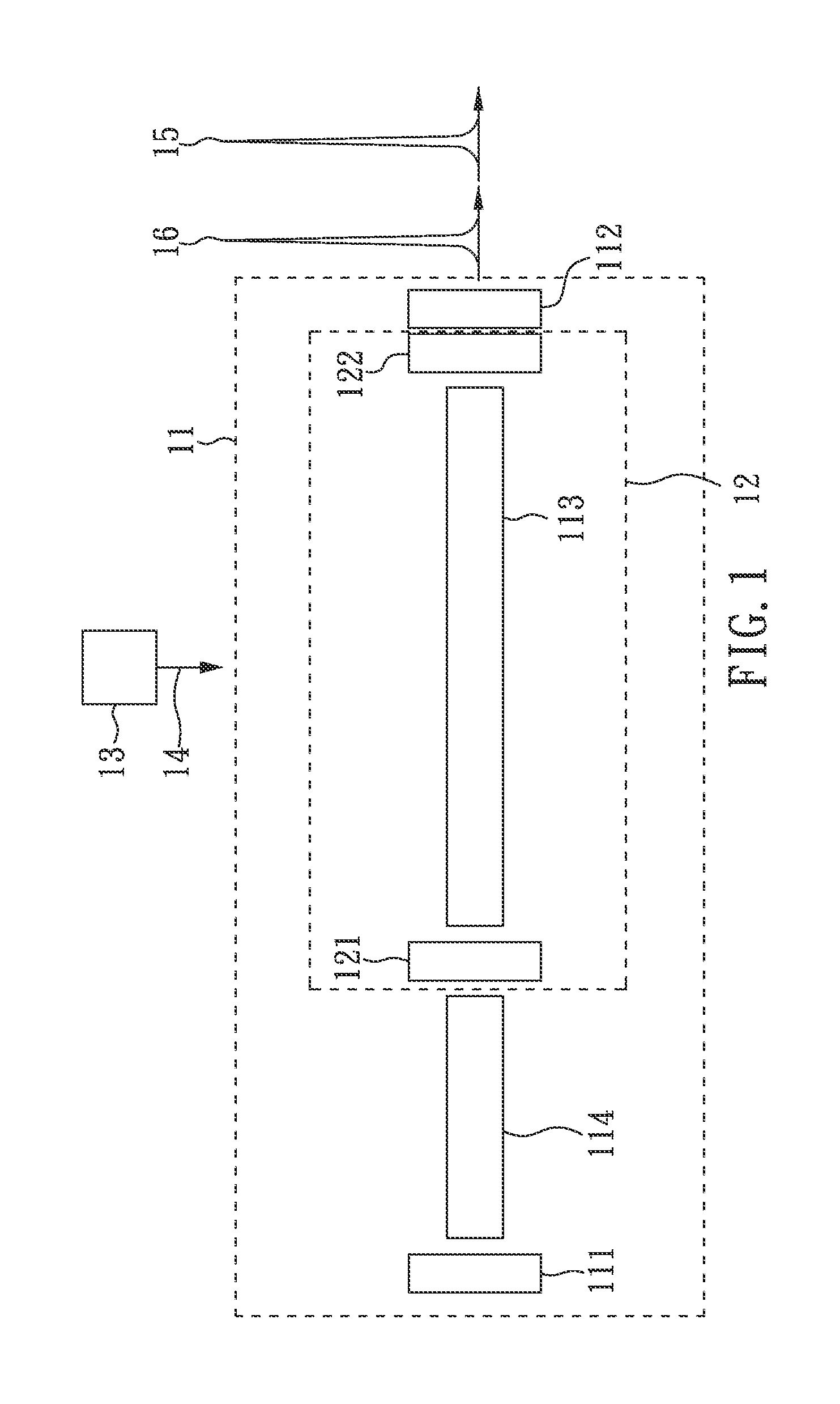
[0044]Please refer to FIG. 3, which is a schematic diagram of the all-fiber Q-switching-induced gain-switched erbium pulse laser system according to the second embodiment of the present invention. As shown FIG. 3, the all-fiber Q-switching-induced gain-switched erbium pulse laser system according to the second embodiment of the present invention includes: a pumping light coupling component 31, a saturable absorber Q-switch fiber 32, a first fiber Bragg grating component 33, a second fiber Bragg grating component 34, a third fiber Bragg grating component 35, an Er3+-doped gain fiber 36 and a fourth fiber Bragg grating component 37.

[0045]Furthermore, as shown FIG. 3, in the all-fiber Q-switching-induced gain-switched erbium pulse laser system of the second embodiment of the present invention, the first fiber Bragg grating component 33, the second fiber Bragg grating component 34, the Er3+-doped gain fiber 36, and the saturable absorber Q-switch fiber 32 form a first laser resonator 30...


PUM


Abstract

The present invention relates to a Q-switching-induced gain-switched erbium pulse laser system, capable of generating erbium laser pulses within the 2.5 μm to 3.0 μm wavelength region, by means of Q-switching operation at 1.6 μm. At first, an Er3+-doped gain medium is pumped and Q-switched at the wavelength region from 1.58 μm to 1.62 μm, so that a Q-switched pulse is formed from the Er3+-doped gain medium. The Q-switched pulse results in an instant positive population inversion between the levels 4I11 / 2 and 4I13 / 2 of the Er3+-doped gain medium, followed by a gain-switched laser pulse at the wavelength region from 2.5 μm to 3.0 μm.

Description

BACKGROUND OF THE INVENTION[0001]1. Field of the Invention[0002]The present invention relates to Q-switching-induced gain-switched erbium pulse laser system, and more particularly, to an laser system employing a Q-switch component to Q-switch an Er3+-doped gain medium, and induce a gain-switched pulse from the Er3+-doped gain medium at the wavelength region from 2.5 μm to 3.0 μm.[0003]2. Description of Related Art[0004]Laser, i.e., light radiation with a narrow range of frequencies, is a collimated, monochromatic, and coherent beam produced by stimulated emission amplification and feedback resonance. It is also well-known that the “resonance structure”, the “gain medium” and “pumping light source” of three essential requirements must be used for generating a laser.[0005]Moreover, since a laser beam has many advantages in optical properties, the laser beam is widely applied in many technical fields. For example, because water molecules absorb photons within the range of wavelength 2....

Claims


Application Information

Patent Timeline
Patent Type & Authority Applications(United States)
IPC IPC(8): H01S3/082H01S3/14H01S3/094
CPCH01S3/0675H01S3/08059H01S3/082H01S3/173H01S3/113H01S3/1608H01S3/0809H01S3/09415
Inventor TSAI, TZONG-YOW
Owner NAT CHENG KUNG UNIV
Why Eureka
Try Eureka