Ignition control device
a control device and ignition technology, applied in the direction of electric control, ignition automatic control, instruments, etc., can solve the problems of difficult control of achieve the effect of effectively controlling the timing of thermal ignition, less energy, and efficient control
- Summary
- Abstract
- Description
- Claims
- Application Information
AI Technical Summary
Benefits of technology
Problems solved by technology
Method used
Image
Examples
embodiment
Effect of Embodiment
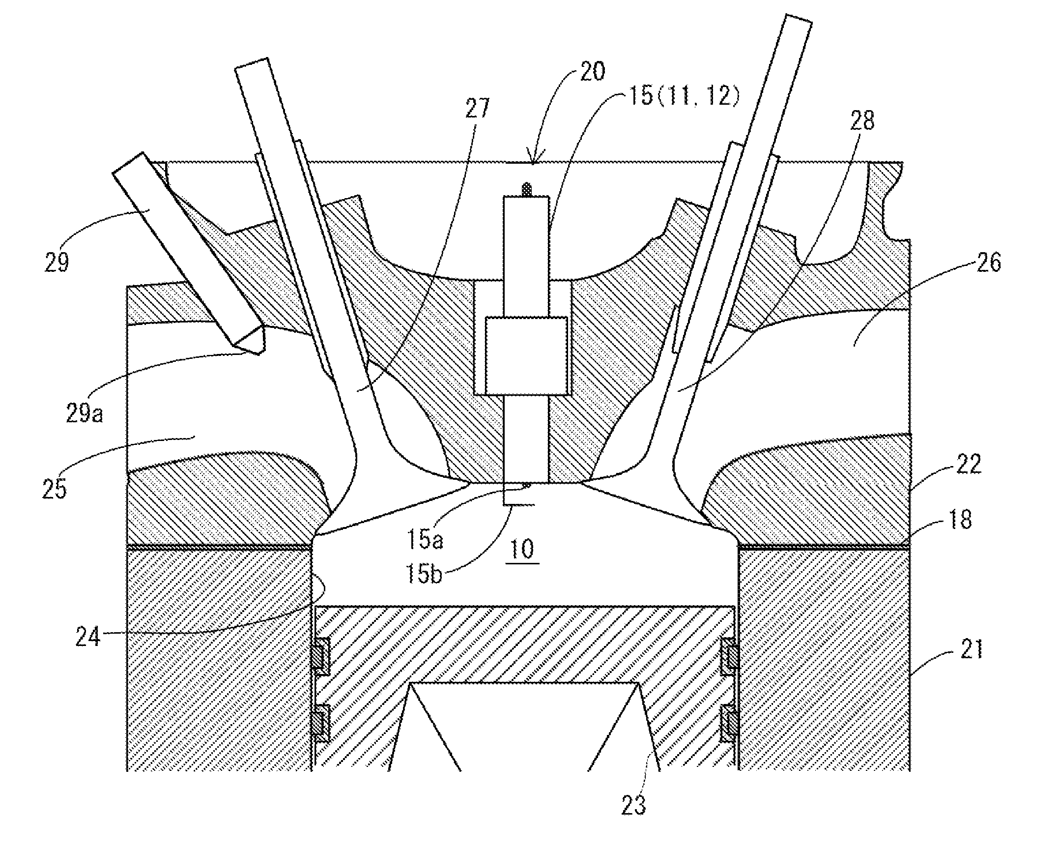
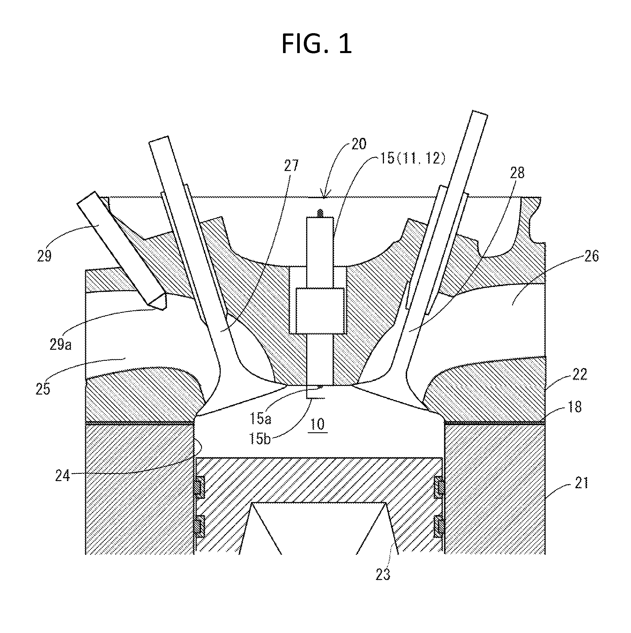
[0066]In the present embodiment, since, in a case in which the peak prior to ignition occurs in the combustion chamber 10, the energy required during the low-temperature oxidation preparation period to change the timing of thermal ignition of the gaseous mixture is remarkably less in comparison to the energy required during the thermal ignition preparation period, the amount of OH radicals in the combustion chamber 10 is increased during the low-temperature oxidation preparation period, thereby the timing of thermal ignition of the gaseous mixture in the combustion chamber 10 is controlled. Accordingly, it becomes possible to efficiently control the timing of thermal ignition of the gaseous mixture in the combustion chamber 10.
[0067]Furthermore, in the present embodiment, since the timing of thermal ignition of the gaseous mixture in the combustion chamber 10 can be efficiently accelerated, large amount of gaseous mixture can be combusted before the gaseous mixtu...
first modified example of embodiment
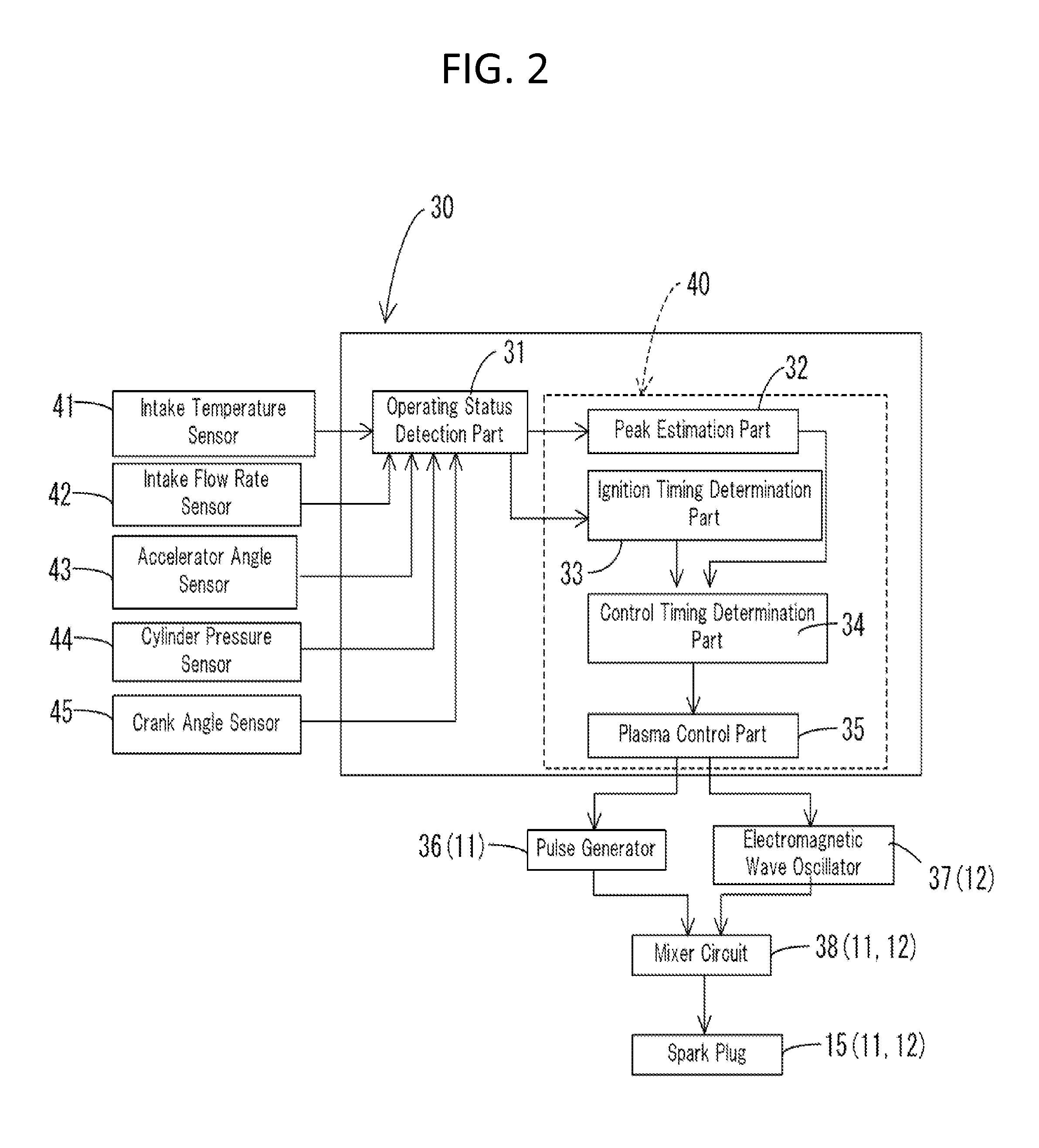
[0070]A first modified example of the present embodiment will be described hereinafter. In the first modified example, the control unit 40 causes the radical amount adjusting units 11 and 12 to adjust the amount of OH radicals to be increased in the combustion chamber 10 during the low-temperature oxidation preparation period in accordance with the intended timing of thermal ignition of the gaseous mixture. In the first modified example, the electromagnetic wave oscillator 37 of the radical amount adjusting units 11 and 12 is controlled so as to increase the increased amount of OH radicals in the combustion chamber 10 in accordance with the degree to which the timing of thermal ignition of the gaseous mixture is accelerated. The electromagnetic wave oscillator 37 is controlled so as to increase the microwave intensity in accordance with the degree to which the timing of thermal ignition of the gaseous mixture is accelerated.
[0071]In the first modified example, since, as described ab...
second modified example of embodiment
[0072]A second modified example of the present embodiment will be described hereinafter. In the second modified example, the control unit 40 causes the radical amount adjusting units 11 and 12 to increase the amount of OH radicals in the combustion chamber 10 only in a case in which the peak prior to ignition occurs. Prior to the estimation operation, the peak estimation part 32 of the control unit 40 performs a determination operation of determining whether or not the peak prior to ignition occurs based on the present operating status of the internal combustion engine 20. The peak estimation part 32 performs the estimation operation only when it has been determined in the determination operation that the peak prior to ignition will occur. If it has been determined in the determination operation that the peak prior to ignition will not occur, the plasma control part 35 does not output the discharge signal nor the radiation signal.
Other Embodiments
[0073]The above described embodiment...
PUM
 Abstract
Description
Claims
Application Information
 - R&D
- Intellectual Property
- Life Sciences
- Materials
- Tech Scout
- Unparalleled Data Quality
- Higher Quality Content
- 60% Fewer Hallucinations
Browse by: Latest US Patents, China's latest patents, Technical Efficacy Thesaurus, Application Domain, Technology Topic, Popular Technical Reports.
© 2025 PatSnap. All rights reserved.Legal|Privacy policy|Modern Slavery Act Transparency Statement|Sitemap|About US| Contact US: help@patsnap.com


