Camera Projection Meshes

a technology of projection meshes and cameras, applied in the field of tridimensional (also), can solve the problems of excessively expensive and slow real-time use of the whole scene, affecting the performance of video surveillance cameras, and the hardware limit on the number of video surveillance cameras. , to achieve the effect of less complex, faster rendering, and increased video projection rendering performan

Inactive Publication Date: 2013-01-24
FORTEM SOLUTIONS
View PDF9 Cites 93 Cited by
  • Summary
  • Abstract
  • Description
  • Claims
  • Application Information

AI Technical Summary

Benefits of technology

[0011]The proposed rendering method increases video projection rendering performance by restricting the rendered geometry to only the surfaces visible to a camera, using a Camera Projection Mesh (hereinafter “CPM”), which is essentially a dynamically-generated simplified mesh that “molds” around the area surrounding each camera. In a typical scene (e.g. large building or city), a CPM is many orders of magnitude less complex than the full scene in terms of number of vertices, triangles or pixels, and therefore many orders of magnitude faster to render than the full scene.
[0013]Then, a mesh is built by creating triangles between the world positions in the framebuffer texture. This effectively creates a mesh molded over the 3D world surfaces visible to the camera. This mesh is stored in a draw buffer that can be rendered using custom vertex and fragment shader programs.
[0016]These meshes have a complexity that can easily be adjusted by the implementation and that is typically much lower than rendering the full scene, resulting in significant reduction in vertex computational load. For cameras with a limited field-of-view (hereinafter “FOV”), the meshes only cover the area actually within the FOV of the camera, so no computational cost is incurred in other areas of the 3D scene resulting in significant reduction in fragment computational load as well.

Problems solved by technology

A problem however arises for complex scenes, composed of a large number of polygons, having a complex object hierarchy or many videos.
Repeating the rendering of the whole scene rapidly becomes excessively expensive and too slow for real-time use.
This approach is however more complex to develop than the previous one and has hardware limits on the number of video surveillance cameras that can be processed in a single rendering pass.
In addition, it still requires rendering the full scene multiple times. Essentially, while this method linearly increases the vertex throughput and scene traversal performance, it does nothing to improve the pixel / fragment performance.
A set of related problems consists in analyzing and visualizing the locations visible from one or multiple viewpoints.
Another example problem consists in visualizing and interactively identifying the optimal locations of video surveillance cameras, to ensure a single or multiple coverage of key areas in a complex security-critical facility.
Unfortunately, published VSA algorithms only handle simple scenarios such as triangular terrains, so they do not generalize to arbitrarily complex 3D models, e.g. indoor 3D models, tunnels and so on.
Furthermore, because they do not take advantage of modern features found in Graphical Processing Units (hereinafter “GPU” or “GPUs”), VSA algorithms cannot interactively process the large 3D models routinely used by engineering and GIS departments, especially those covering entire cities or produced using 3D scanners and LIDAR.

Method used


Image

  • Camera Projection Meshes
  • Camera Projection Meshes
  • Camera Projection Meshes

Examples


Embodiment Construction

[0023]Novel methods for rendering tridimensional (3D) areas or scenes based on video camera images and video sequences will be described hereinafter. Although the invention is described in terms of specific illustrative embodiments, it is to be understood that the embodiments described herein are by way of example only and that the scope of the invention is not intended to be limited thereby.

[0024]The creation and use of a Camera Projection Mesh (hereinafter “CPM”) has four main phases:

[0025]a. the position map creation phase;

[0026]b. the mesh draw buffer creation phase;

[0027]c. the mesh rendering phase; and

[0028]d. the mesh invalidation phase.

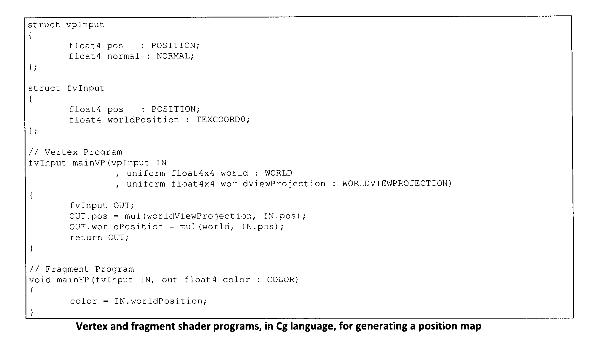
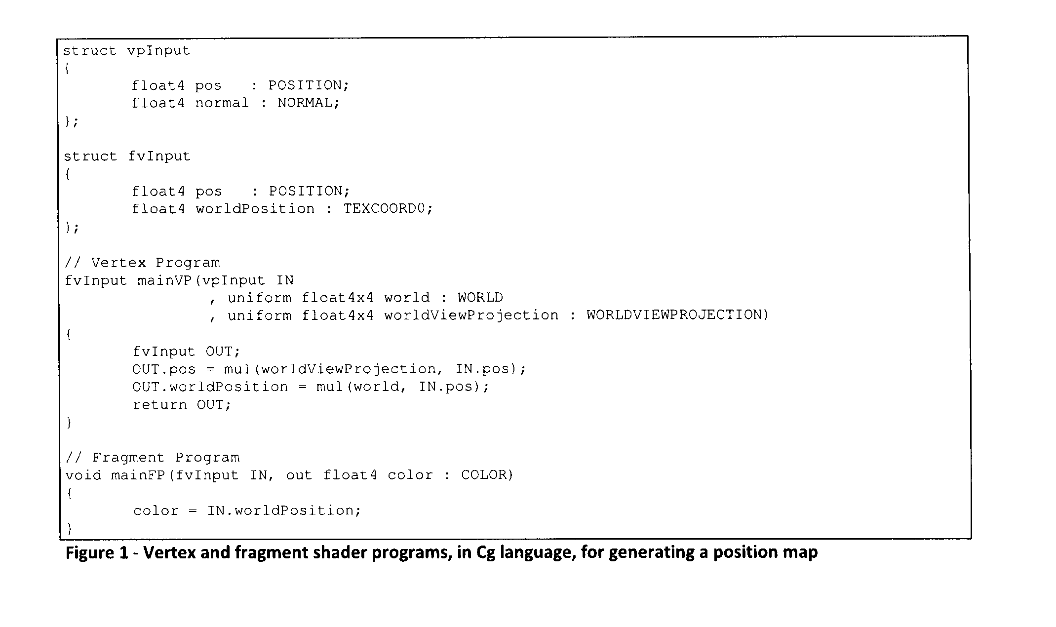
[0029]Position Map Creation Phase

[0030]First a position map is created from the point of view of the video camera. A position map is a texture that contains coordinates (x, y, z, w) components instead of color values (red, green, blue, alpha) in its color components. It is similar to a depth map which contains depth values instead of color val...


PUM


Abstract

A 3D rendering method is proposed to increase the performance when projecting and compositing multiple images or video sequences from real-world cameras on top of a precise 3D model of the real world. Unlike previous methods that relied on shadow-mapping and that were limited in performance due to the need to re-render the complex scene multiple times per frame, the proposed method uses, for each camera, one Camera Projection Mesh (“CPM”) of fixed and limited complexity per camera. The CPM that surrounds each camera is effectively molded over the surrounding 3D world surfaces or areas visible from the video camera. Rendering and compositing of the CPMs may be entirely performed on the Graphic Processing Unit (“GPU”) using custom shaders for optimal performance. The method also enables improved view-shed analysis and fast visualization of the coverage of multiple cameras.

Description

CROSS-REFERENCE TO RELATED APPLICATIONS[0001]The present patent application claims the benefits of priority of commonly assigned U.S. Provisional Patent Application No. 61 / 322,950, entitled “Camera Projection Meshes” and filed at the United States Patent and Trademark Office on Apr. 12, 2010; the content of which is incorporated herein by reference.FIELD OF THE INVENTION[0002]The present invention generally relates to tridimensional (also referred to as “3D”) rendering and analysis, and more particularly to high-performance (e.g. real-time) rendering of real images and video sequences projected on a 3D model of a real scene, and to the analysis and visualization of areas visible from multiple view points.BACKGROUND OF THE INVENTION[0003]It is often desirable for software applications that perform 3D rendering (e.g. games, simulations, and virtual reality) to project video textures on a 3D scene, for instance to simulate a video projector in a room. Another exemplary application cons...

Claims


Application Information

Patent Timeline
Patent Type & Authority Applications(United States)
IPC IPC(8): H04N13/02
CPCG06T17/20G06T15/40
Inventor COSSETTE-PACHECO, ALEXANDRELAFORTE, GUILLAUMELAFORTE, CHRISTIAN
Owner FORTEM SOLUTIONS
Why Eureka
Try Eureka