Gear train lubricating device

a gear train and lubricating technology, which is applied in the direction of gear systems, machines/engines, efficient propulsion technologies, etc., can solve the problems of reducing air resistance, power loss in such a gear system, and increasing the negative influence of fuel consumption of aircraft engines such as jet engines or gas turbine engines, so as to reduce power loss, suppress air resistance, and reduce air resistance

Active Publication Date: 2013-01-31
KAWASAKI HEAVY IND LTD
View PDF5 Cites 35 Cited by
  • Summary
  • Abstract
  • Description
  • Claims
  • Application Information

AI Technical Summary

Benefits of technology

[0015]In the present invention, a peripheral speed at a pitch circle of each of the pair of gears is set to 50 to 120 m / sec, for example. Outlet ports are formed in the outer peripheral wall of the shroud such that each outlet port is provided at a respective position that is away from the meshing position of the gears and that is 90°±15° forward from the meshing position in the rotation direction of a corresponding one of the gears. Therefore, advantageous effects of reducing both lubricating oil agitation resistance and air resistance exerted on the gears of the gear train, which rotates with such a high peripheral speed, can be sufficiently provided.
[0016]Accordingly, in the gear train lubricating device of the present invention, the outlet port for the lubricating oil is formed in the outer peripheral wall of the shroud at a position that is 90°±15° forward in the rotation direction of the gear from the meshing position of the gear. In the shroud, at the position where the outlet port is formed, the lubricating oil that has sufficiently been rectified swirls at a suitable flow rate, and great centrifugal force in a discharging direction is exerted on the swirling lubricating oil. Such a suitably positioned outlet port is formed such that the area of opening of the outlet port is small, which is advantageous in terms of suppressing air resistance exerted on the gear, and yet the outlet port allows the lubricating oil to be efficiently discharged therethrough by a preset discharge amount. This makes it possible to reduce the air resistance exerted on the gear, and to suppress an increase in lubricating oil agitation resistance, the increase being caused when an excessive amount of lubricating oil remains within the shroud. As a result, power loss can be reduced.

Problems solved by technology

Power loss in such a gear system is mainly caused by air resistance and lubricating oil agitation resistance, which occur when the gears rotate.
In this case, power loss in a gear system that is caused by the air resistance and the lubricating oil agitation resistance also increases, which results in an increase in negative influence on the fuel consumption of an aircraft engine such as a jet engine or a gas turbine engine.
The shrouding system is disposed in close proximity to the teeth of the gears, and thereby suppresses the generation of the above-described swirling air flow at the front face of each gear and reduces the air resistance.

Method used


Image

  • Gear train lubricating device
  • Gear train lubricating device
  • Gear train lubricating device

Examples


Embodiment Construction

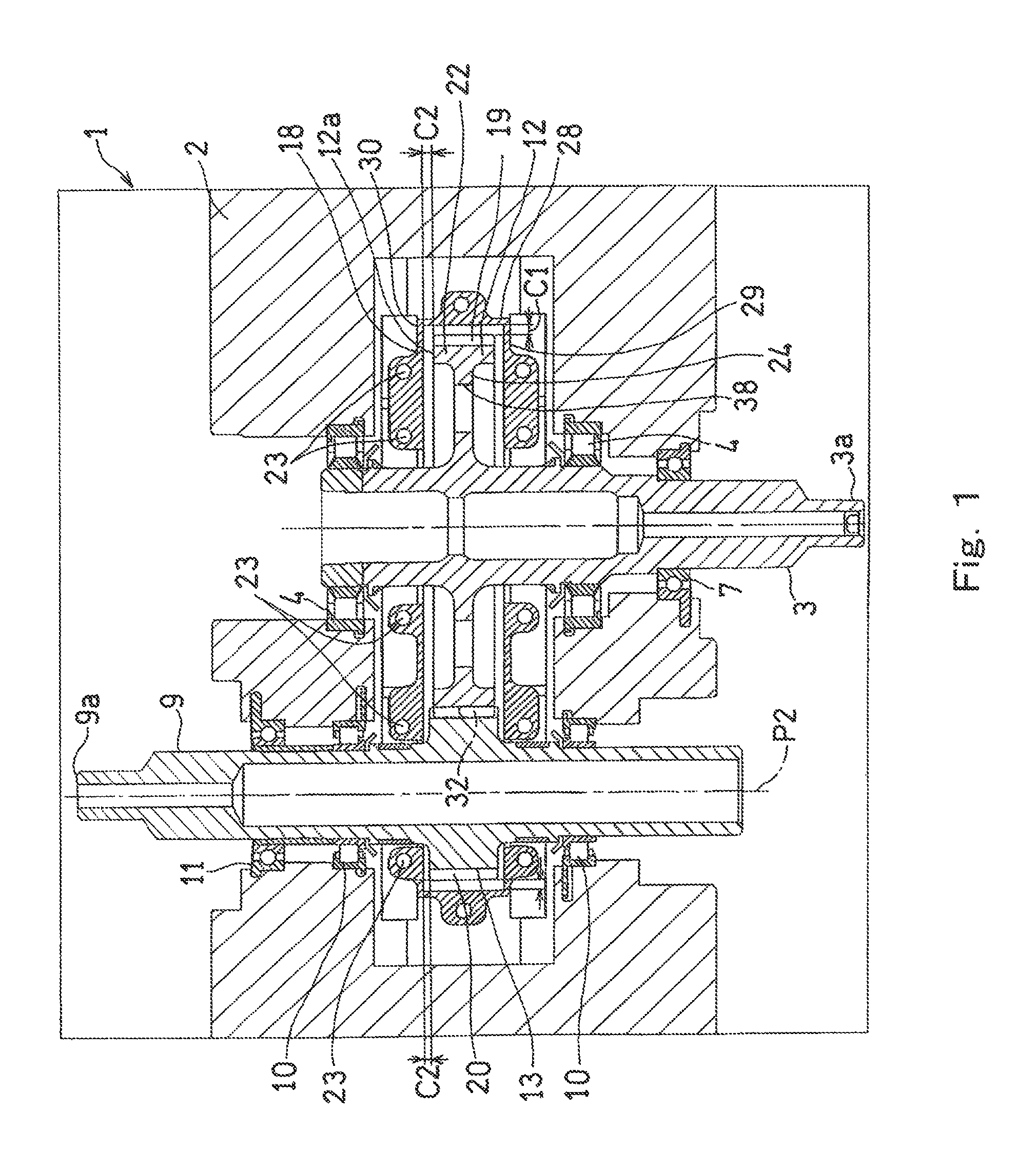
[0024]Hereinafter, a preferred embodiment of the present invention is described with reference to the accompanying drawings.

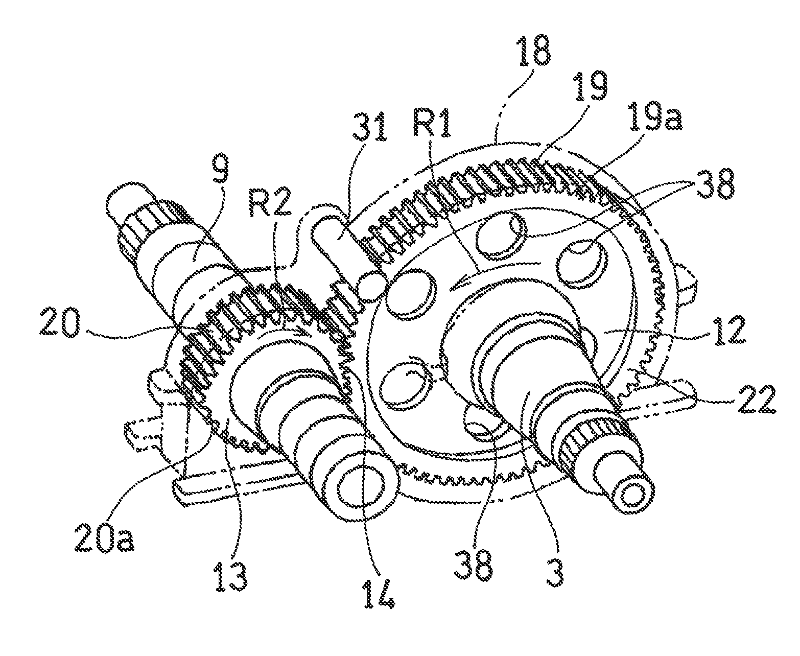
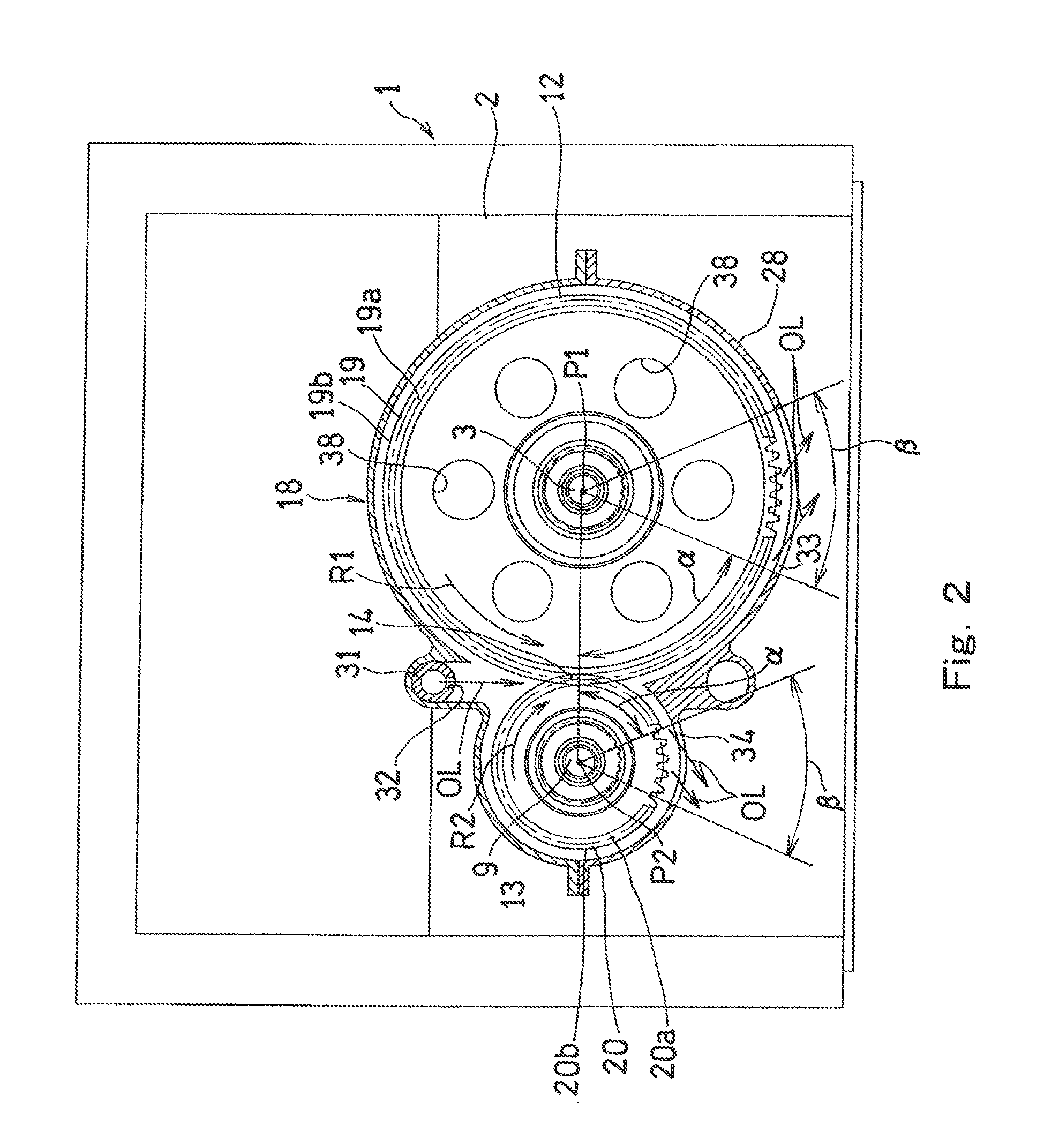
[0025]FIG. 1 is a horizontal sectional view of a gear system according to an embodiment of the present invention. As shown in FIG. 1, a gear system 1 according to the present embodiment includes an input shaft 3 and an output shaft 9. The input shaft 3 is rotatably supported by a bearing housing 2 via three bearings which are two bearings 4 and a bearing 7. One end 3a of the input shaft 3 is connected to a jet engine or a different power source via a power transmission device which is not shown. An input gear 12, which is a spur gear, is integrally formed on the input shaft 3. A rim 22 is formed at the outer periphery of the input gear 12. The width of the rim 22 in an axial direction is greater than that of a disc 24 positioned at the inner side of the rim 22. Spur teeth 19 are formed at the outer diameter surface of the rim 22.

[0026]Meanwhile, the output shaf...


PUM


Abstract

A gear train lubricating device configured to supply lubricating oil OL to a gear included in a gear train is provided. The gear train lubricating device includes: a shroud covering, among components constituting the gear, at least teeth of the gear; and a lubricating oil supply port through which the lubricating oil OL is supplied to a meshing position of the gear. The shroud has an outlet port formed therein, through which the supplied lubricating oil OL is discharged. The outlet port is formed in a portion of the shroud that is positioned radially outward from the gear, such that the outlet port is disposed at an angular position that is 90°±15° forward from the meshing position in a rotation direction R1 of the gear.

Description

TECHNICAL FIELD[0001]The present invention relates to a lubricating device for a gear train in a gear system such as a gearbox or a high-speed gear mechanism used in a gas turbine engine or a jet engine.BACKGROUND ART[0002]Such a gear system as mentioned above includes a lubricating oil supply port and a lubricating oil outlet port for use in lubricating and cooling down the gears. The lubricating oil supply port is used for spraying lubricating oil onto the gears, and the lubricating oil outlet port is used for collecting, with an oil scavenging pump, the lubricating oil that has been used for lubricating and cooling down the gears. Power loss in such a gear system is mainly caused by air resistance and lubricating oil agitation resistance, which occur when the gears rotate. Particularly in the case of an aircraft engine, the air resistance is great since the gear train rotates at a relatively high speed. Moreover, in aircrafts developed in recent years, electrification of various ...

Claims


Application Information

Patent Timeline
Patent Type & Authority Applications(United States)
IPC IPC(8): F16H57/02F16H1/06F16H57/04
CPCF01D25/18F02C7/32F05D2260/4031Y10T74/2186F16H57/0423F16H57/0495Y02T50/671F16H57/0409Y02T50/60
Inventor ARISAWA, HIDENORIIMAI, HIDEYUKIGOI, TATSUHIKONISHIMURA, MOTOHIKO
Owner KAWASAKI HEAVY IND LTD
Why Eureka
Try Eureka