Rotationally symmetrical tool for cutting material surfaces and method for the production of such a tool

a technology of rotating symmetry and cutting material, which is applied in the direction of shearing tools, shearing apparatus, abrasives, etc., can solve the problems of low number of cover surfaces of ring disks involved in the metal-cutting process, limited to two, and production is very laborious, so as to prevent fluttering of disks or ring disks

Active Publication Date: 2013-01-31
GERD EISENBLATTER GMBH
View PDF5 Cites 16 Cited by
  • Summary
  • Abstract
  • Description
  • Claims
  • Application Information

AI Technical Summary

Benefits of technology

[0032]In order to prevent fluttering of the disks or ring disks during rotating operation, adhesive is applied close to the incisions of the disks or ring disks in some sections during the production of the tool. The adhesive can be applied before or after the production step in which the disks or in disks are slid into each other. The gluing in some sections can occur in form of individual adhesive points or adhesive beads. It is advantageous when a supporting disk is used to fix the disks or ring disks to the same by means of adhesive. The lowermost layer of the mutually stacked disks or ring disks is glued together with the upper side of the supporting disk. The adhesive can be applied either in some sections or in a planar fashion on the supporting disk or the disks or ring disks, or on both. Suitable adhesives are polyurethane, cold or hot adhesives.

Problems solved by technology

The disadvantageous aspect of the tools known from the prior art is the low number of cover surfaces of the ring disks involved in the metal-cutting process, which is limited to two.
Furthermore, production is very laborious because the shapes of the incisions differ in the two ring disks and the sliding and interlocking of the two multiply incised ring disks cannot be automated in a cost-effective manner.

Method used


Image

  • Rotationally symmetrical tool for cutting material surfaces and method for the production of such a tool
  • Rotationally symmetrical tool for cutting material surfaces and method for the production of such a tool
  • Rotationally symmetrical tool for cutting material surfaces and method for the production of such a tool

Examples


first embodiment

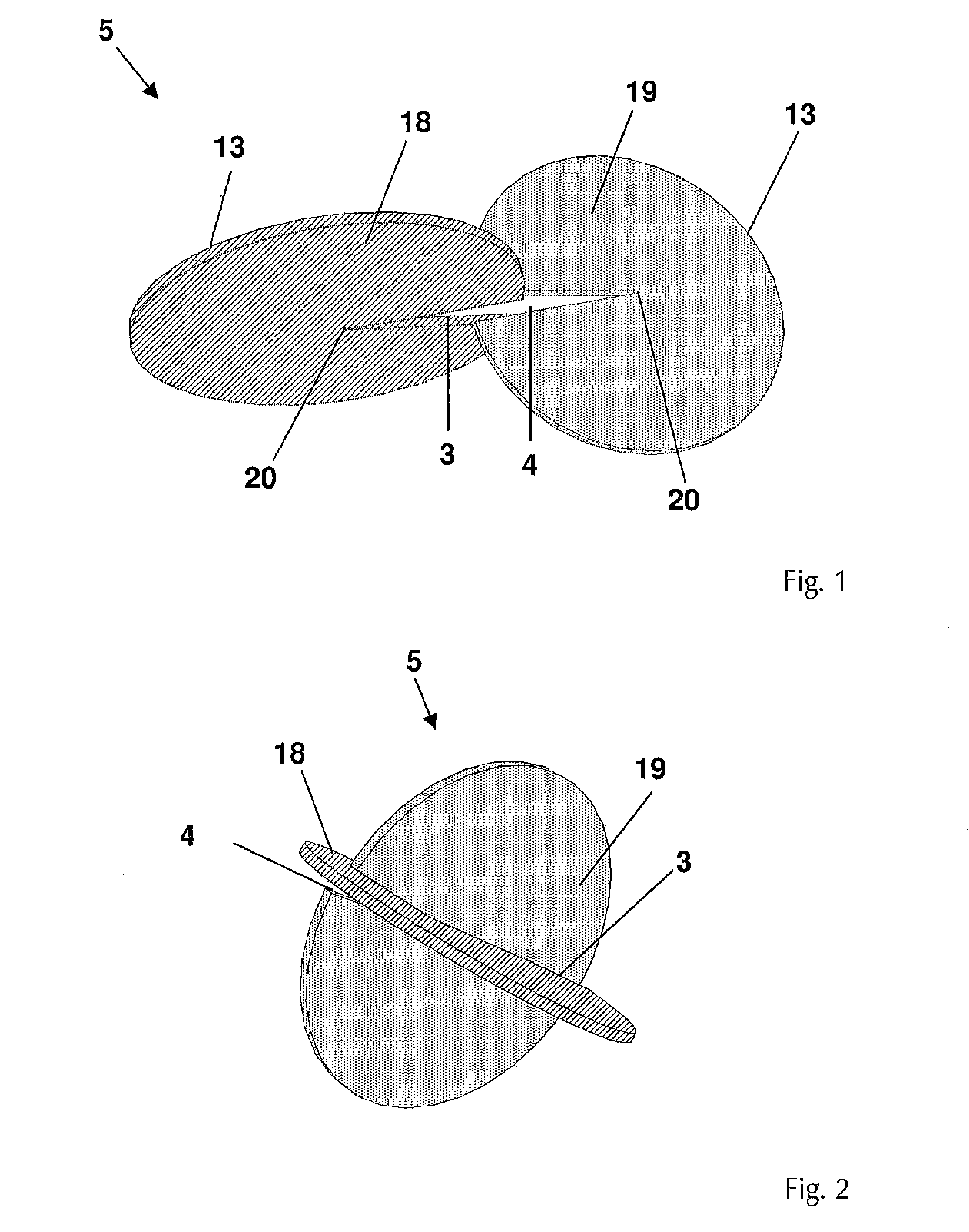
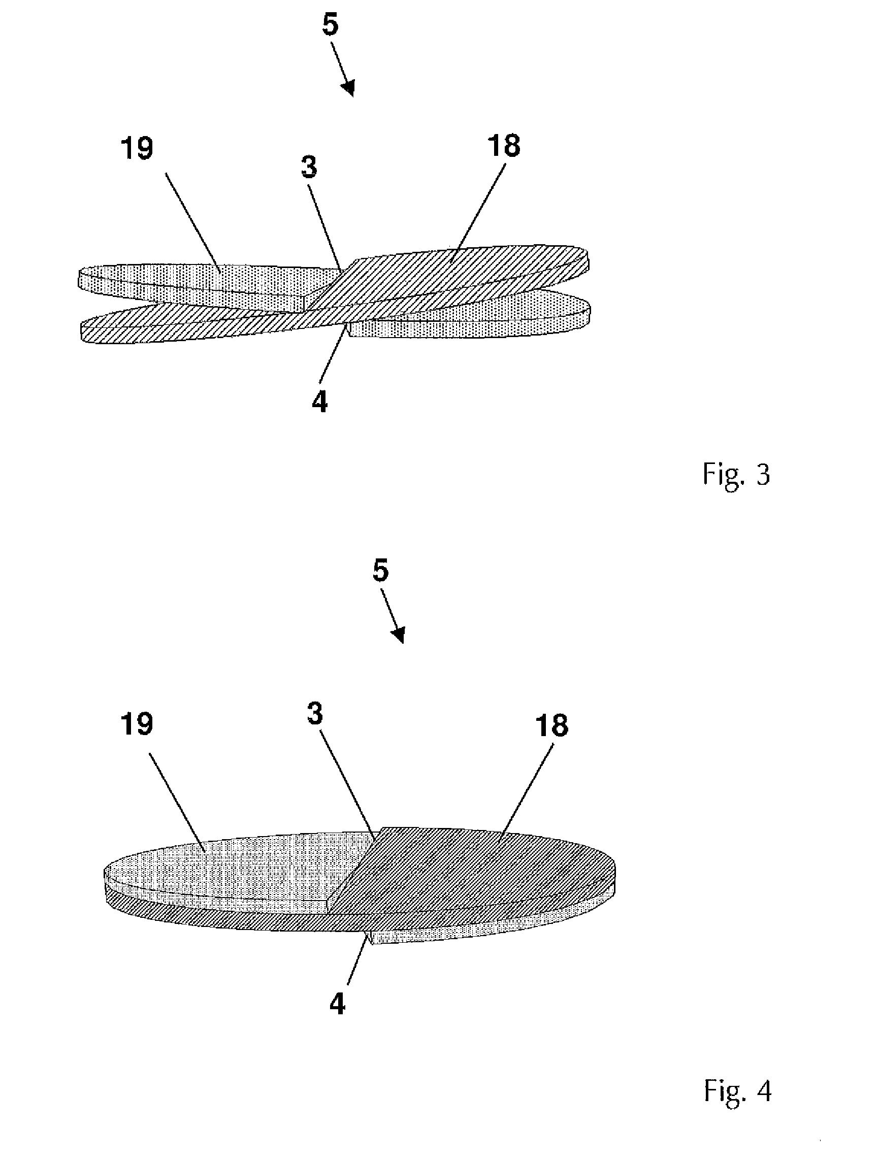
[0045]FIG. 5 shows a circular ring disk 10 arranged for metal-cutting with a circular centric opening 11. The ring disk 10 comprises a radially extending incision 12 of constant width which extends from the outer circumference 13 of the ring disk 10 up to its inner circumference 14. The ring disk 10 consists of a support 15 made of a cotton / polyester mix fabric and an abrasive agent as a material machining coating 16 which contains bonded ceramic grain.

[0046]FIG. 6 shows a second tool 6 which consists of three (n=3) mutually stacked and overlapping ring disks 10′, 10″ and 10′″ according to FIG. 5. The production method of the tool 6 is performed in an analogous fashion to the production steps as shown in FIGS. 1 to 4. However, two ring disks 10′ and 10″ are slid simultaneously into the incision 12′″ of the third ring disk 10′″, folded towards one another and twisted against one another. The width of the incision 12′″ is large enough for the ring disks 10′ and 10″, being placed on t...

second embodiment

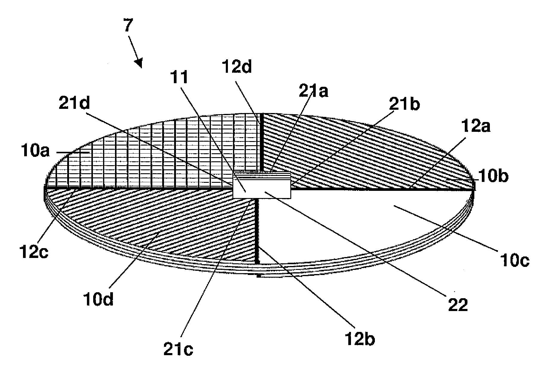
[0048]FIG. 7 shows four circular ring disks with the ring disks being arranged as a felt ring disk 10a, a grinding ring disk 10b, a nonwoven ring disk 10c and a polishing ring disk 10d. The felt ring disk 10a consists of a polyester support which is covered with a felt material. The grinding ring disk is arranged as a cotton support with corundum bonded in resin. The nonwoven ring disk 10c consists of a nonwoven material saturated with zirconium corundum, and the polishing ring disk 10d is a polishing cloth provided with a polishing paste. The ring disks 10a to 10d have the same configuration and all comprise a wedge-shaped incision 12a to 12d from the outer circumference 13 to the inner circumference 14. The otherwise circular centric openings 11 are respectively provided with a straight side, which are used as adjusting aids 21a to 21d. The adjusting aids 21a to 21d are disposed offset by 90° in relation to the respective incisions 12a to 12d. At their narrowest points where they...

fourth embodiment

[0051]FIG. 9 shows four circular ring disks 10a to 10d according to a The felt ring disk 10a, the grinding ring disk lob, the nonwoven ring disk 10c and the polishing ring disk 10d are composed of materials as explained in the description of FIG. 7. The incisions 12a to 12d reach from the outer circumference 13 up to the inner circumference 14. The width of the wedge-shaped incisions 12a to 12d decreases from the inner circumference 14 to the outer circumference, with the narrowest point of the incisions 12a to 12d corresponding to the thickness of two mutually stacked ring disks 10a to 10d. The centric openings 11 are semicircular in all ring disks 10a to 10d. The straight side of the semicircular openings 11 is respectively used as adjusting aids 21a to 21d, The incisions 12a to 12d are disposed in four ring disks 10a to 10d to be offset by 0, 90, 180 and 270° to the straight side of the semicircular adjusting aids 21a to 21d. When the four ring disks 10a to 10d are stacked above...


PUM

PropertyMeasurementUnit
speedaaaaaaaaaa
speedaaaaaaaaaa
angleaaaaaaaaaa

Abstract

A tool has disks or ring disks arranged for metal-cutting, which are stacked on top of each other in an overlapping fashion and engage into each other at their incisions which reach from the outer circumference up to the center point of the disks or the inner circumference of the ring disks. The incisions of the directly adjacent disks or ring disks are respectively angularly offset by 360°/n, with n being the number of the disks or ring disks. A production method is also provided for such a tool, in which the disks or ring disks are incised up to the center point or inner circumference, are completely slid into each other at the incisions, folded towards one another and displaced until an angular offset of the incisions of 360°/n is produced.

Description

CROSS REFERENCE TO RELATED APPLICATIONS[0001]Applicant claims priority under 35 U.S.C.§119 of German Application No. 10 2011 108 859.1 filed Jul. 28, 2011, the disclosure of which is incorporated by reference.BACKGROUND OF THE INVENTION[0002]1. Field of the Invention[0003]The invention relates to a rotationally symmetrical tool for cutting material surfaces with several disks or ring disks arranged for metal-cutting, which comprise an incision originating from the outer circumference, comprise a common rotational axis and are stacked in a partly overlapping manner on top of one another in such a way that a portion of one respective disk or ring disk comes to lie on top through the incision of a disk or ring disk disposed above, with the incisions of the disks or ring disks being angularly offset. Furthermore, the invention relates to disks or ring disks with which the tool is arranged, and a method for the production of said tool.[0004]2. Description of the Related Art[0005]Generic ...

Claims


Application Information

Patent Timeline
Patent Type & Authority Applications(United States)
IPC IPC(8): B26D1/14B23P11/00
CPCB24D9/08Y10T29/49826B24D18/00B24D13/14Y10T83/9403
Inventor EISENBLAETTER, GERD
Owner GERD EISENBLATTER GMBH
Why Eureka
Try Eureka