Vehicle underfloor structure

a technology for vehicles and underfloors, applied in vehicle arrangements, roofs, transportation and packaging, etc., to achieve the effect of increasing air resistan

Active Publication Date: 2013-01-31
NISSAN MOTOR CO LTD
View PDF0 Cites 30 Cited by
  • Summary
  • Abstract
  • Description
  • Claims
  • Application Information

AI Technical Summary

Benefits of technology

[0005]The conventional underfloor structure can prevent an increase in air resistance due to the water drain holes formed into an elliptical shape elongated in the front-back direction of the vehicle (refer to FIG. 4 of Patent Document 1). However, if a large amount of water and mud water penetrates inside of the under cover, the water and mud water tend to be stored in the under cover because the opening areas of the water drain holes are small and do not have a sufficient drainage capacity.
[0006]Further, in the conventional underfloor structure, a large part of the opening of each water drain hole is exposed on the cover surface of the under cover formed in a traveling airflow direction (refer to FIG. 5 of Patent Document 1). Therefore, if the opening areas of the water drain holes are increased to improve the drainage capacity, the traveling airflow is easily introduced through the water drain holes because the exposed opening areas on the cover surface are also increased. As a result, a turbulent flow around the water drain holes is caused and air resistance is increased.
[0007]The present invention has been made in view of the above-described conventional problems. It is an object of the present invention to provide a vehicle underfloor structure in which an increase in air resistance is suppressed during driving while a drainage capacity in an under cover is ensured so that an aerodynamic property of the entire vehicle can be improved.

Problems solved by technology

However, if a large amount of water and mud water penetrates inside of the under cover, the water and mud water tend to be stored in the under cover because the opening areas of the water drain holes are small and do not have a sufficient drainage capacity.

Method used


Image

  • Vehicle underfloor structure
  • Vehicle underfloor structure
  • Vehicle underfloor structure

Examples


example 1

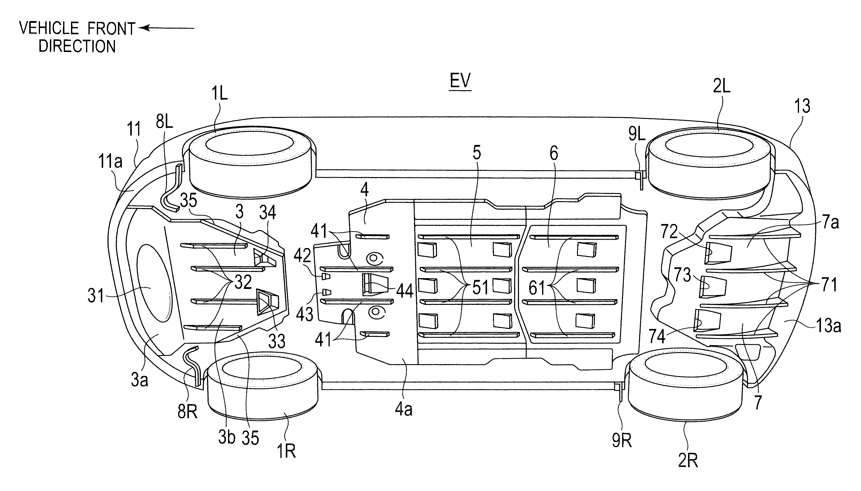
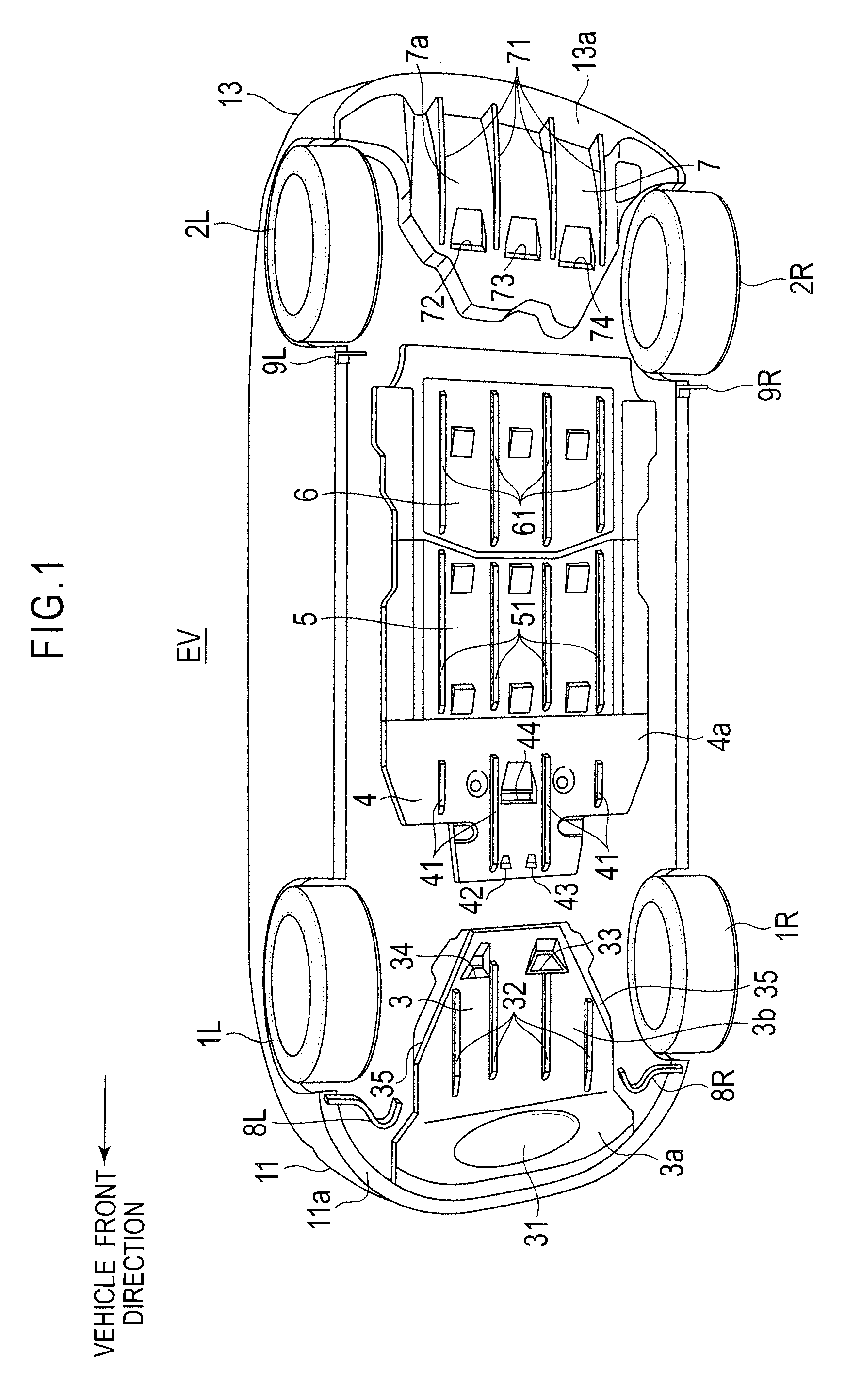
[0029]FIG. 1 is a perspective view showing the entire underfloor structure according to Example 1 applied to an electric vehicle. As shown in FIG. 1, the entire underfloor structure of an electric vehicle EV of Example 1 includes a pair of front tires 1L and 1 R, and a pair of rear tires 2L and 2R. The underfloor structure further includes a front under cover 3, a motor room rear under cover 4, a first battery under cover 5, a second battery under cover 6 and a rear under cover 7 (an example of under covers). Still further, the underfloor structure includes a pair of front deflectors 8L and 8R, and a pair of rear deflectors 9L and 9R.

[0030]The pair of front tires 1L and 1R are not only steering wheels but also driving wheels elastically fixed to a vehicle body via a front suspension link (not shown in the figure). The pair of rear tires 2L and 2R are elastically fixed to the vehicle body via a rear suspension (not shown in the figure) such as a trailing type suspension.

[0031]The fro...

example 2

[0111]Hereinafter, the vehicle underfloor structure according to Example 2 of the present invention will be explained with reference to the drawings. Note that the same constitutions as Example 1 are indicated by the common reference numerals and the overlapped explanations thereof will not be repeated.

[0112]The entire underfloor structure of the electric vehicle EV according to Example 2 also includes the pair of front tires 1L and 1R, and the pair of rear tires 2L and 2R as shown in FIG. 1. The underfloor structure further includes the front under cover 3, the motor room rear under cover 4, the first battery under cover 5, the second battery under cover 6 and the rear under cover 7. Still further, the underfloor structure includes the pair of front deflectors 8L and 8R (an airflow adjusting structure), and the pair of rear deflectors 9L and 9R.

[0113]The two battery under covers 5 and 6 cover the bottom surface of the battery unit 16 (a plane projected region), and are connected to...


PUM


Abstract

A vehicle underfloor structure includes under covers (3, 4, 5, 6, 7) that cover an underside of a vehicle, and drain members (D) provided in the under covers (3, 4, 5,6, 7). The drain members (D) each include: a front inclined wall (21) provided with a water drain opening (33, 34, 42, 43, 44, 72, 74); and a rear inclined wall (22). A recess is formed in each under cover in a front-back direction of the vehicle in such a manner that a first interior angle (θ1) formed by the front inclined wall is larger than a second interior angle (θ2) formed by the rear inclined wall and a length of the front inclined wall is different from a length of the rear inclined wall.

Description

TECHNICAL FIELD[0001]The present invention relates to a vehicle underfloor structure in which an underside surface of a vehicle is covered with an under cover provided with a drain member.BACKGROUND ART[0002]Patent Document 1 discloses a vehicle underfloor structure in which an underside surface is covered with an under cover provided with a drain member. In such an underfloor structure, the underside surface is provided with recesses projecting inward, and water drain holes partly overlapped with peripheral portions on the front side of the recesses.[0003]In the conventional underfloor structure, the water drain holes are formed into an elliptical shape elongated in a front-back direction of the vehicle, and the recesses are partly overlapped with the elliptical holes. Thus, air flowing along a bottom surface of the under cover is hardly introduced into the under cover. In other words, Patent Document 1 aims at providing the under cover including the water drain holes that hardly l...

Claims


Application Information

Patent Timeline
Patent Type & Authority Applications(United States)
IPC IPC(8): B62D25/20B62D35/02
CPCB62D35/02Y02T10/82Y02T10/88
Inventor ONODERA, TAKESHITERASHIMA, YASUTSUNE
Owner NISSAN MOTOR CO LTD
Why Eureka
Try Eureka