Method and device for testing solenoid valves

a solenoid valve and valve body technology, applied in the direction of short-circuit testing, measurement devices, instruments, etc., can solve the problems of time-consuming and possible depressurisation of the system, and achieve the effect of reducing the time-consuming and time-consuming method for testing solenoid valves

Active Publication Date: 2013-01-31
MAHLE INT GMBH
View PDF9 Cites 9 Cited by
  • Summary
  • Abstract
  • Description
  • Claims
  • Application Information

AI Technical Summary

Benefits of technology

[0018]Analysing the waveform of the current flowing through the windings of the solenoid valve over time is a reliable method for identifying a stuck mechanical pin in the valve.

Problems solved by technology

This known method for testing solenoid valves is time consuming and it is sometimes not desirable to pressurize the system in a self test by opening the valve as it may not be possible to depressurise the system again if the solenoid is faulty.

Method used


Image

  • Method and device for testing solenoid valves
  • Method and device for testing solenoid valves
  • Method and device for testing solenoid valves

Examples


first embodiment

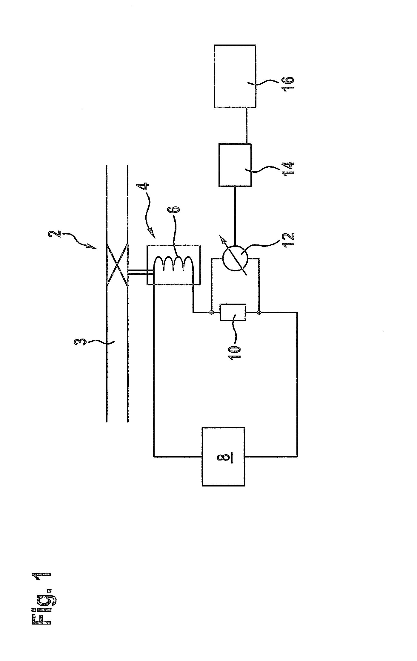
[0023]FIG. 1 shows a schematic view of device for testing a solenoid valve 2 arranged at a fluid conduit 3.

[0024]The solenoid valve 2 comprises a solenoid drive 4 with at least one winding 6. The solenoid drive 4 is configured to open the solenoid valve 2 when an electric current flows through said winding 6.

[0025]The test device further comprises a voltage generator 8, which is electrically connected to the winding 6 and configured to apply a short pulse of voltage, which is not long enough to open the solenoid valve 2, to the winding 6. At least one shunt 10 is arranged in the electrical connection between the voltage generator 8 and the winding 6. According to Ohm's law a voltage, which is proportional to the electrical current flowing through said shunt 10, is generated between the endings of the shunt 10. The generated voltage is measured by means of a voltage meter 12 electrically connected to the ends of the shunt 10.

[0026]The voltage meter 12 is electrically connected to an ...

second embodiment

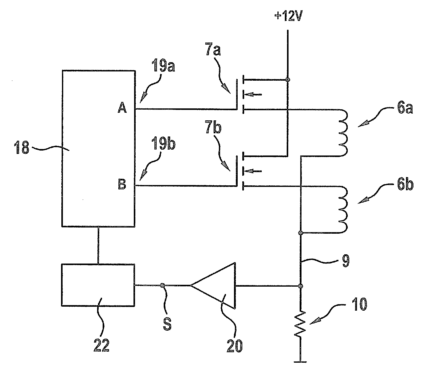
[0040]FIG. 3 shows a schematic view of the test device which allows to test two solenoid valves 2.

[0041]From the solenoid valves 2 to be tested and the respective solenoid drives 4 only the windings 6a, 6b are shown in FIG. 3.

[0042]A voltage may be selectively applied to each of the windings 6a, 6b by means of a control unit 18, which may be a microprocessor. The voltage is selectively output at terminals 19a, 19b of the control unit 18 and supplied to the windings 6a, 6b by respectively assigned transistors 7a, 7b so that the control unit 18 does not need to provide the full current flowing through the windings 6a, 6b.

[0043]A shunt 10 is located in a common ground line 9 of the windings 6a, 6b and the voltage which is generated between the ends of the shunt 10 according to Ohm's law is amplified by an amplifier 20 and input into an analogue-digital-converter 22, which is configured for converting the amplified voltage to digital data. The digital data is supplied to the control u...


PUM


Abstract

A device for testing a solenoid valve includes: a voltage generator for applying a short pulse of voltage, which is not long enough to open the solenoid valve, to the windings of the solenoid valve; a current meter configured for measuring the current flowing through the windings of the solenoid valve; and an analysis device which is configured for analysing the current measured by the current meter for detecting a potential fault of the solenoid valve.

Description

BACKGROUND OF THE INVENTION[0001]1. Field of the Invention[0002]The present invention is directed to a method and a device for testing at least one solenoid valve.[0003]2. Description of the Related Art[0004]Self test functionality is an already known feature. The purpose of these functions is to give the end user as well as the production engineer an indication if one or more of the components in the system are faulty.[0005]When it comes to mechanical solenoid valves the functionality is usually verified by opening the solenoid valve in the system. By using built in pressure sensors and temperature probes it is possible to monitor if the solenoid opens or not. This method tests (a) if the solenoid is connected correctly and there are no open or short circuits in either wiring, solenoids or electronics, and (b) if the correct valve actually opens if the solenoid is energized.[0006]This known method for testing solenoid valves is time consuming and it is sometimes not desirable to pr...

Claims


Application Information

Patent Timeline
Patent Type & Authority Applications(United States)
IPC IPC(8): G01R31/327G01R31/72
CPCG01R31/06G01R31/025G01R31/2829G01R31/72G01R31/52
Inventor LEIF, THYSSEN
Owner MAHLE INT GMBH
Why Eureka
Try Eureka