Methods of making organic photovoltaic cells having improved heterojunction morphology

a technology of photovoltaic cells and heterojunctions, applied in the field of organic photovoltaic solar cells, can solve the problems of increasing the price of ito, reducing the device performance, and unable to meet the requirements of high-performance, high-performance, and high-performance applications, and achieve the effect of improving light absorption

Active Publication Date: 2013-02-14
RGT UNIV OF MICHIGAN
View PDF3 Cites 17 Cited by
  • Summary
  • Abstract
  • Description
  • Claims
  • Application Information

AI Technical Summary

Benefits of technology

[0014]The present technology also contemplates methods of making a photovoltaic material by two-step evaporation of solvent through surface encapsulation and induced alignment, where the photovoltaic material is designed to include a light trapping feature. Thus, in such an embodiment, the second gas permeable stamp used for the second evaporation step has surface topographies (e.g., in the form of periodic grids). Such topographies, when imprinted into the second material (e.g., electron acceptors) during the second evaporation step and over-coated with metal electrode, can produce the light trapping effect desirable for thin film solar cells to improve light absorption by the organic semiconductors.

Problems solved by technology

Though widely used, ITO faces several challenges for low-cost, high performance, large-area, and flexible applications.
The price of ITO has increased due to the limited supply of indium and the increasing demand from the rapidly expanding LCD display market.
The migration of indium from ITO into an adjacent or nearby organic active material layer can reduce the device performance.
Moreover, ITO is not adequate for flexible applications because ITO has poor mechanical strength.
In addition to TCE, another important issue in commercial development of OSC devices pertains to morphology control of organic photoactive material layers.

Method used


Image

  • Methods of making organic photovoltaic cells having improved heterojunction morphology
  • Methods of making organic photovoltaic cells having improved heterojunction morphology
  • Methods of making organic photovoltaic cells having improved heterojunction morphology

Examples


Embodiment Construction

[0039]The following description of technology is merely exemplary in nature of the subject matter, manufacture and use of one or more inventions, and is not intended to limit the scope, application, or uses of any specific invention claimed in this application or in such other applications as may be filed claiming priority to this application, or patents issuing therefrom. A non-limiting discussion of terms and phrases intended to aid understanding of the present technology is provided at the end of this Detailed Description.

[0040]The headings (such as “Introduction” and “Summary”) and sub-headings used herein are intended only for general organization of topics within the present disclosure, and are not intended to limit the disclosure of the technology or any aspect thereof. In particular, subject matter disclosed in the “Introduction” may include novel technology and may not constitute a recitation of prior art. Subject matter disclosed in the “Summary” is not an exhaustive or co...


PUM

PropertyMeasurementUnit
wavelengthsaaaaaaaaaa
sizeaaaaaaaaaa
thickaaaaaaaaaa

Abstract

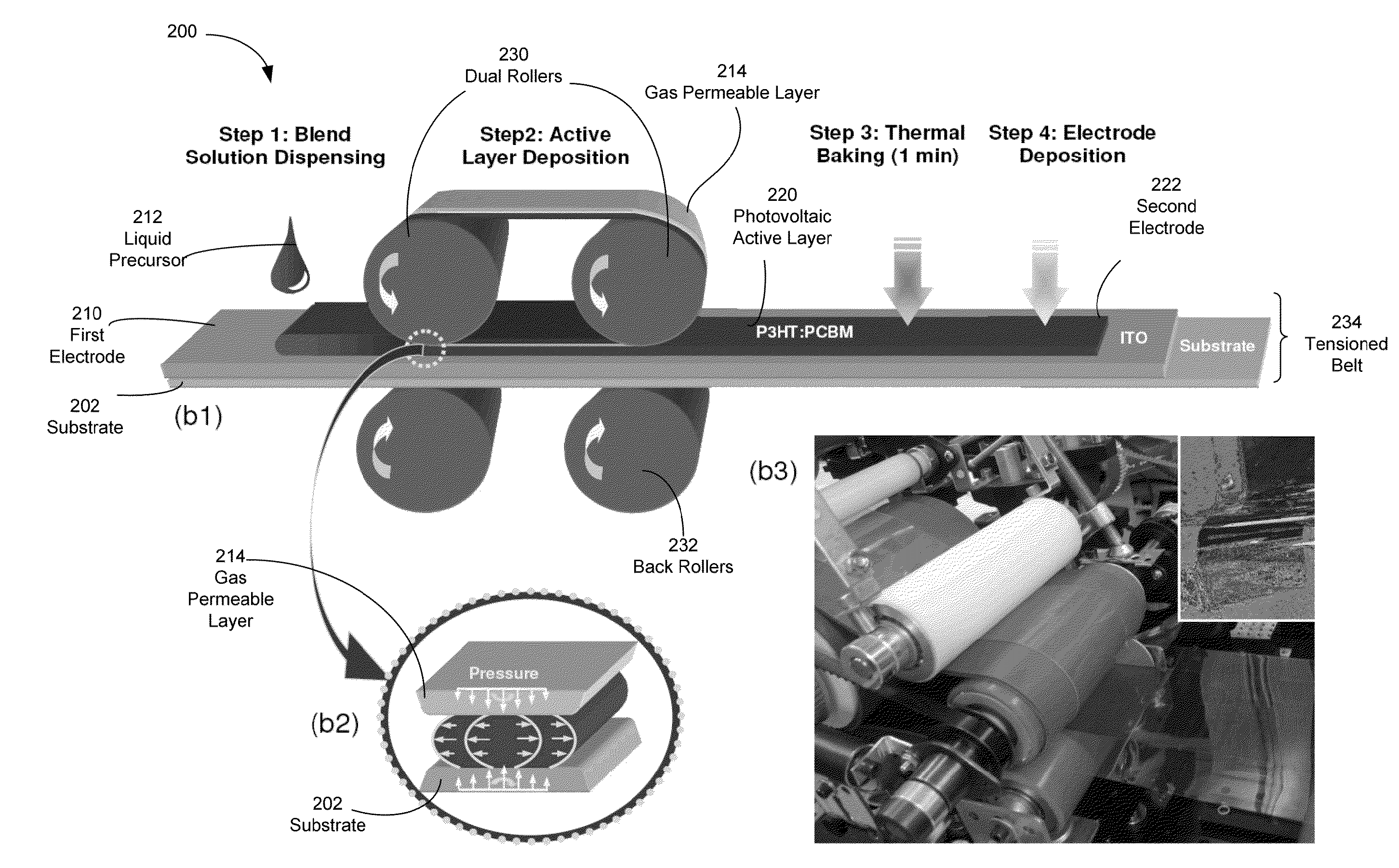
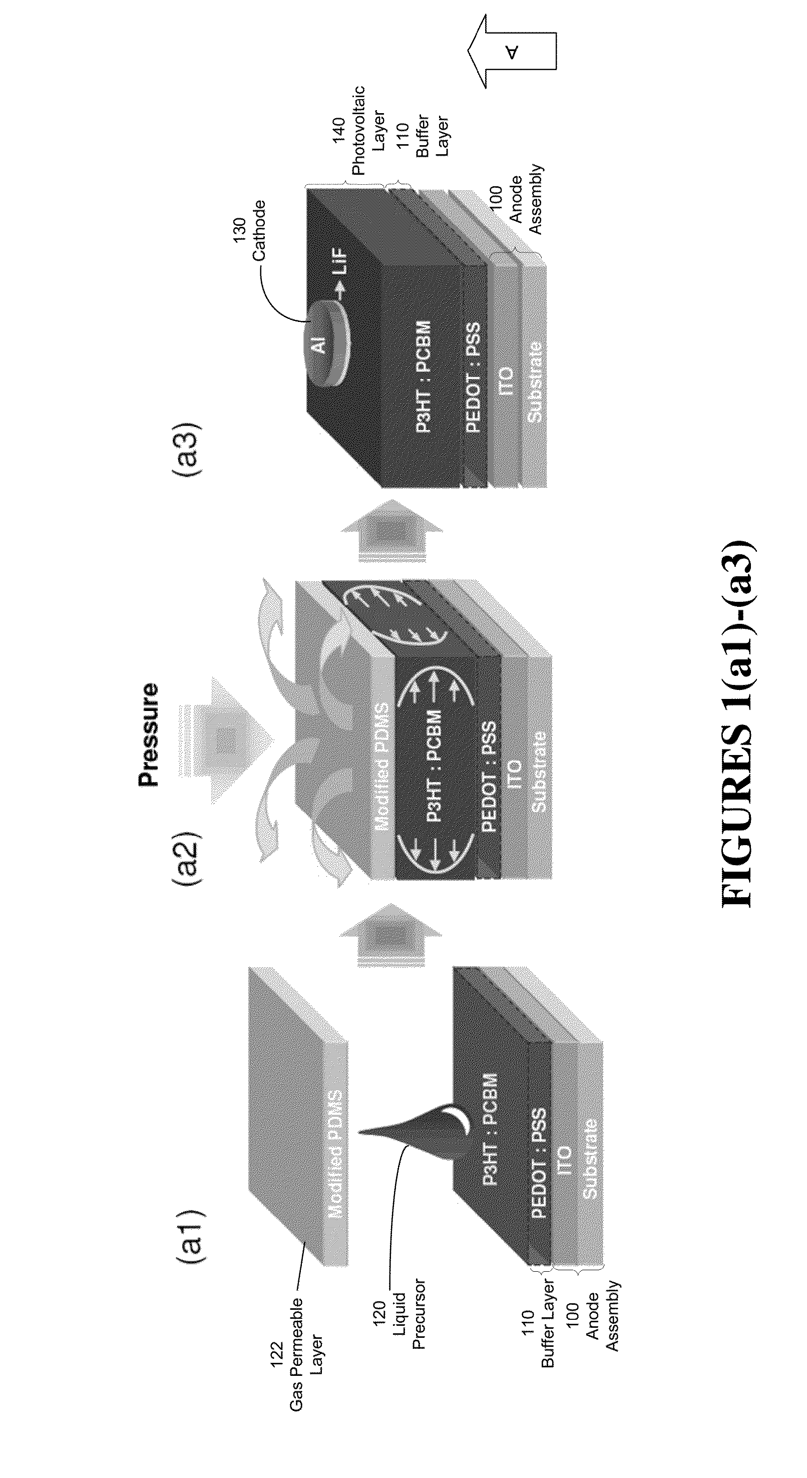
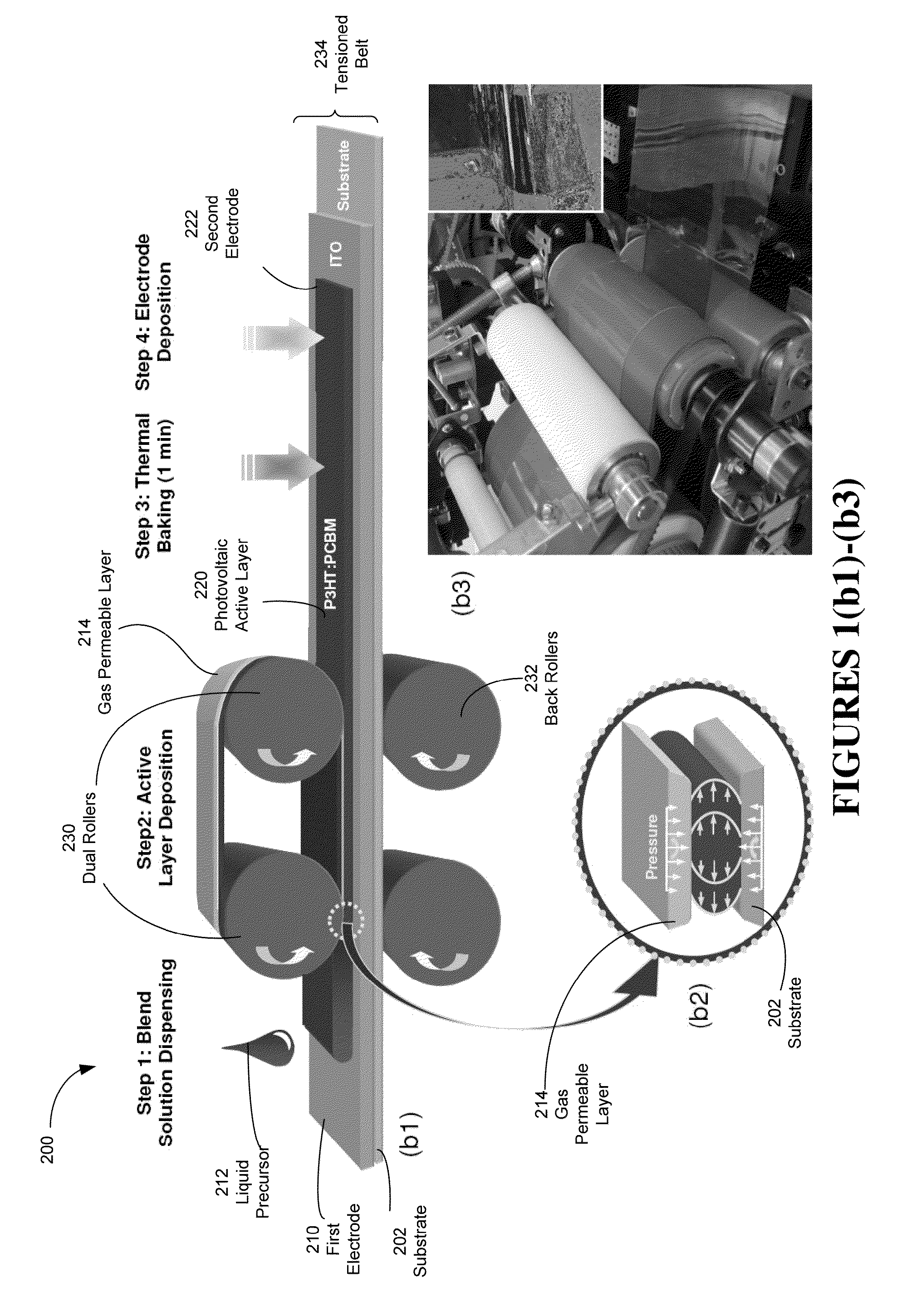
Methods of making a photovoltaic device with an organic liquid precursor having electron donor, electron acceptor, and liquid carrier are provided. The liquid precursor is applied to an electrode. A gas permeable layer/stamp contacts and applies pressure to the organic liquid precursor removing liquid carrier to form a solid active material with uniform interpenetrating network domains of electron donor/acceptor materials. A two-step process is also contemplated. A liquid precursor with either electron donor or acceptor is applied to an electrode, contacted under pressure with a first stamp having a nanoscale pattern, thus forming a solid with a patterned surface. Then, a second liquid precursor with the other of the electron donor or acceptor is applied to the patterned surface, contacted with a second stamp under pressure to form the active material. A transparent conducting electrode with material nanograting can be formed. The methods also include continuous processing, like roll-to-roll manufacturing.

Description

CROSS-REFERENCE TO RELATED APPLICATIONS[0001]This application claims the benefit of U.S. Provisional Application No. 61 / 311,919, filed on Mar. 9, 2010. The entire disclosure of the above application is incorporated herein by reference.GOVERNMENT RIGHTS[0002]This invention was made with U.S. government support under EECS0836584 awarded by the National Science Foundation and 70NANB8H8134 awarded by the National Institute of Standards and Technology. The U.S. government has certain rights in the invention.FIELD[0003]The present technology provides methods of making organic photovoltaic solar cells, for example, by a roll-to-roll process to improve donor-acceptor heterojunction morphology and power conversion efficiency.INTRODUCTION[0004]This section provides background information related to the present disclosure which is not necessarily prior art.[0005]Cost effective and highly efficient renewable energy is becoming ever more important due to rising energy prices and the serious issu...

Claims


Application Information

Patent Timeline
Patent Type & Authority Applications(United States)
IPC IPC(8): H01L51/48H01L51/44
CPCH01L51/0012H01L51/0036H01L51/0037Y02E10/549H01L51/448H01L2251/308Y02E10/52H01L51/4253H10K71/191H10K85/113H10K85/1135H10K30/30H10K30/88H10K2102/103H10K30/50
Inventor PARK, HUI JOONGUO, LINGJIE JAY
Owner RGT UNIV OF MICHIGAN
Why Eureka
Try Eureka