
Method and apparatus for detecting moisture on metal and other surfaces, including surfaces under thermal insulation

a technology for thermal insulation and metal, applied in the direction of measurement devices, material electrochemical variables, instruments, etc., can solve the problems of large financial losses, manufacturing downtime, and leak detection due to corrosive failure often too late, so as to achieve significant reduction of the cost of detailed inspection and testing

Inactive Publication Date: 2013-02-14
FUNAHASHI MIKI
View PDF0 Cites 18 Cited by
  • Summary
  • Abstract
  • Description
  • Claims
  • Application Information

AI Technical Summary

Benefits of technology

This patent is about a device that can track how often and how long water is in contact with steel surfaces in different structures, like pipelines and tanks. By monitoring this data, the device can help assess the risk of corrosion and prioritize which parts of the structure need to be inspected. This can save money by reducing the cost of detailed inspection and testing.

Problems solved by technology

The corrosion of pipes, tanks and various equipment under thermal insulation has been a significant problem in the petrochemical and other industries.
When such metal structures are covered with thermal insulation, leak detection due to corrosive failure is often too late because the corrosion under insulation (CUI) cannot be visually inspected without removing the insulation material.
The lengthy and high cost of corrosion repairs and inspection results in huge financial losses and manufacturing downtime.
In ideal situations, the insulation system should be water tight; however, the failure of water tightness occurs in some areas, resulting in water intrusion.
Even in non-sponge-like insulator materials, when water intrudes under the insulator, it may accumulate in the lower portion of the pipelines, tanks, or equipment, resulting in corrosion and leaks.
It is not economical, and highly time consuming, to visually insect multiple sections of a pipeline by removing the insulation.
Furthermore, inspections are difficult due to the limited access in highly congested areas.
Moreover, when the visual inspection is carried out by removing the insulation, the integrity of the water tightness may be disrupted.
However, with such systems water leaks in non-monitored areas may be occurring without detection.
In addition, moisture due to condensation on the pipe surface or if only a small amount of water is present under the insulation, the amount of moisture may not be sufficient for detection purposes even though this amount of water is sufficient for localized CUI.
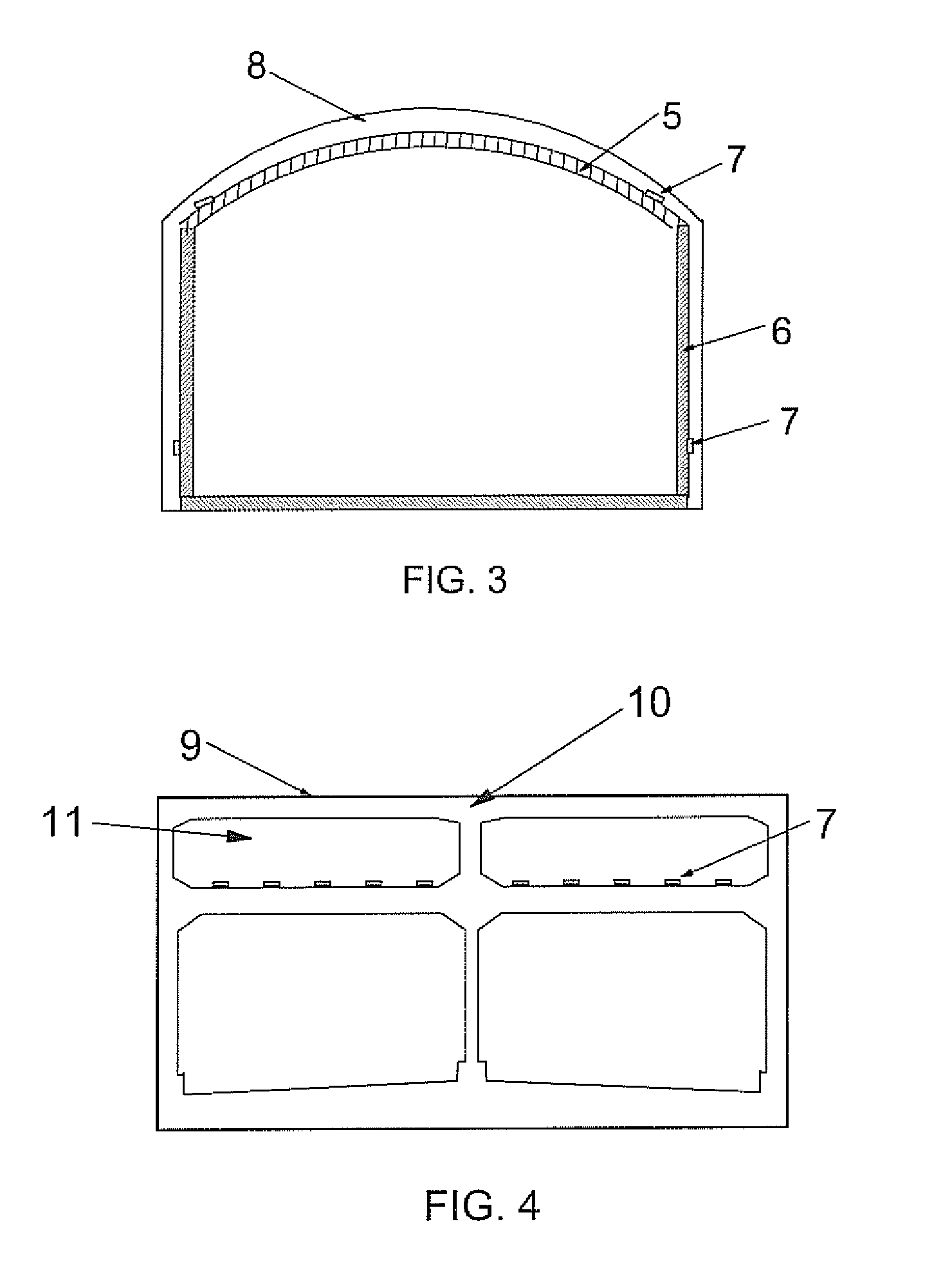
Another serious problem caused by water leaks is associated with tunnel structures.
However, water leaks in the waterproof membranes may develop due to the defects in some areas caused by structural damage, soil movement or deterioration due to age.
The water may cause severe corrosion of the reinforcing steel bar (rebar) in the concrete, particularly in the roof and walls.
When chlorides in water penetrate into concrete and reach to the rebar, the corrosion products of the rebar expand, resulting in concrete cracks and spalls.
If the spalled concrete falls on pedestrians, automobiles or trains inside the tunnels, it may cause traffic disruption and serious injury.
However, due to defects in the sheathing system, material deterioration due to aging, or failure of the anchoring system, water tightness may fail.
Since the cable inside cannot visually inspected, expensive non-destructive inspection devices are used when the outside of the cable is accessible.
However, when cables are embedded in concrete, inspection is not possible until the failure of the cable occurs.

Method used


Image

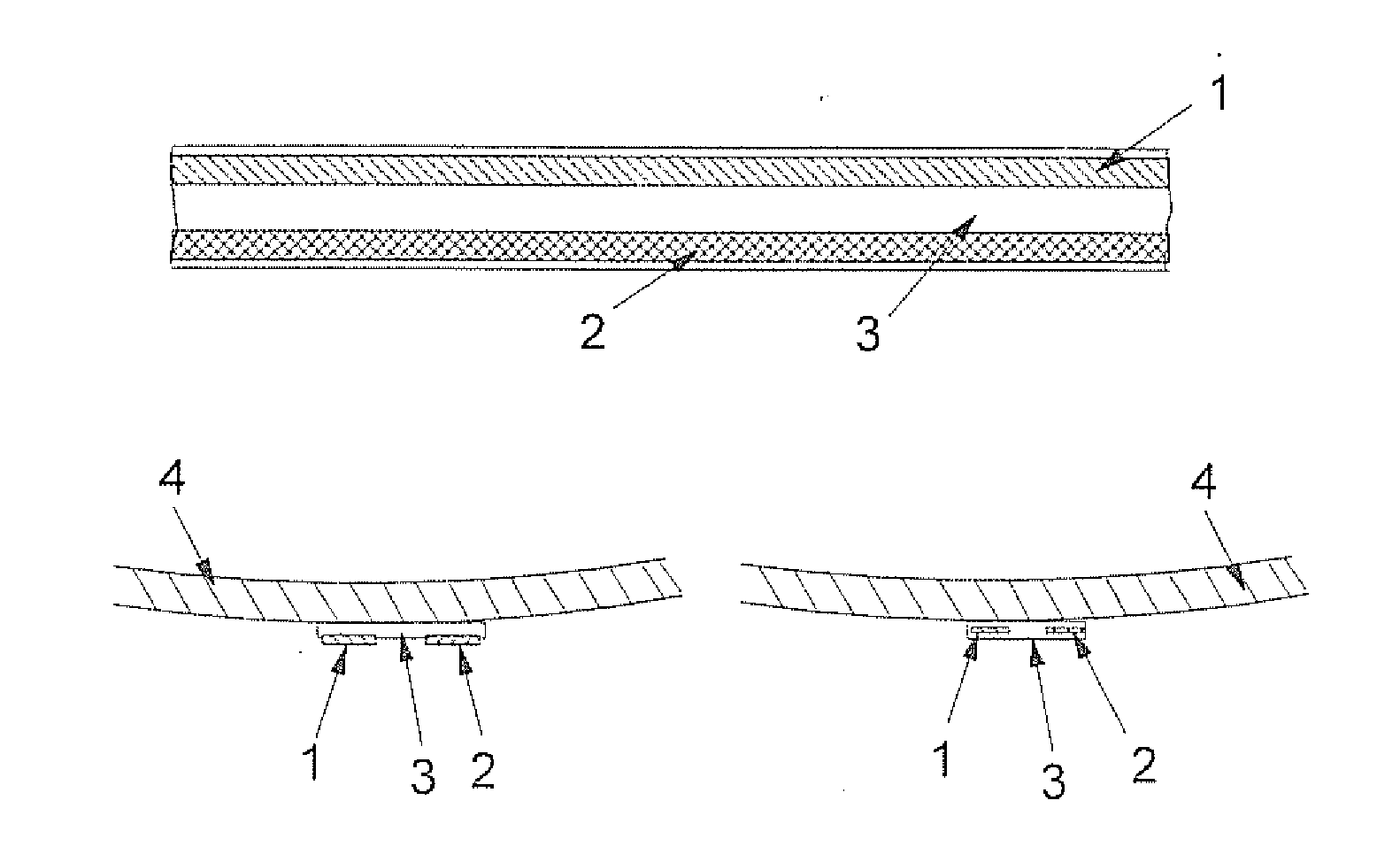
  • Method and apparatus for detecting moisture on metal and other surfaces, including surfaces under thermal insulation
  • Method and apparatus for detecting moisture on metal and other surfaces, including surfaces under thermal insulation
  • Method and apparatus for detecting moisture on metal and other surfaces, including surfaces under thermal insulation

Examples


Embodiment Construction

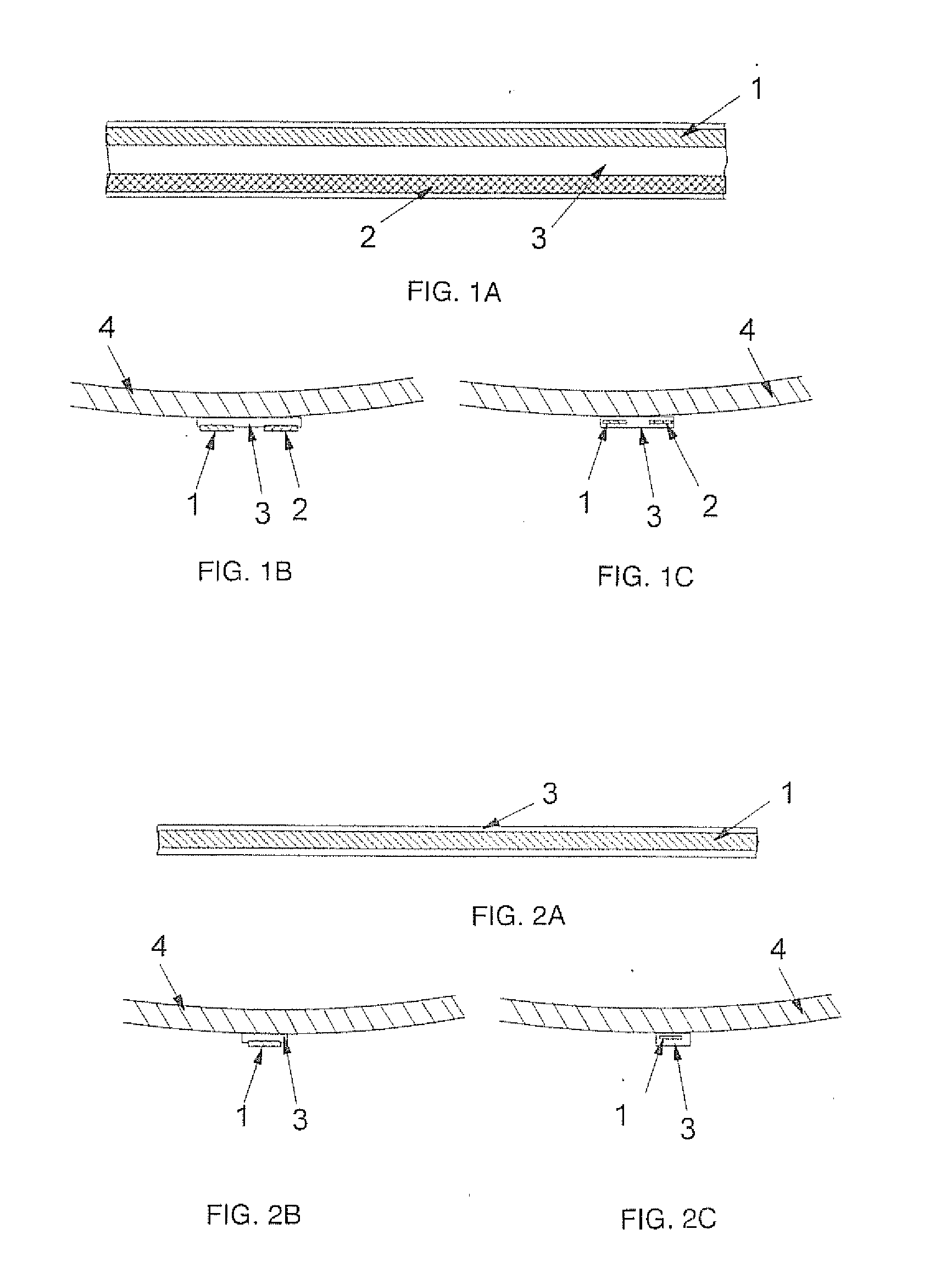
[0026]By way of background, in a given environment such as water, one metal will be either more noble or more active than the other, based on how strongly its ions are bound to the surface. Using the water as an electrolyte, the more noble metal will take electrons from the more active one. The resulting mass flow or electrical current can be measured to establish a hierarchy of materials in the medium of interest. This hierarchy is called a galvanic series, and can be a very useful in predicting and understanding corrosion.

[0027]When two dissimilar metals are surrounded by a non-electrolyte or dry material, they do not develop a potential difference between them. When the two dissimilar metals are immersed in an electrolyte, however, the potential difference between them can be measured. The present invention uses this principle. When the two dissimilar metal tapes are spaced apart and not in direct electrical contact, they show different potentials or voltage in electrolyte as ind...


PUM


Abstract

Systems and methods are disclosed for detecting the presence of water on or in pipelines, tanks, equipment and other structures, including insulated structures which may be subject to corrosion under insulation, or CUI. Two dissimilar, spaced-apart metals are coupled at least indirectly to a structure to be monitored, and apparatus for detecting a potential difference between the two dissimilar metals, thereby indicating that water is present as an electrolyte. In CUI applications, at least one of the dissimilar metals is attached to, or embedded within, a water-absorbing insulator or other material coupled to or surrounding the structure. The water-absorbing material may be provided in the form of a tape attached to the surface of a metal component fanning the structure. In some embodiments, the structure to be monitored may itself incorporate a ferrous metal component which is used as one of the dissimilar metals.

Description

FIELD OF THE INVENTION[0001]This invention relates to water detection and, in particular, to the detection of moisture on metal pipelines, tanks, equipment and structures which cannot readily be inspected by detecting the voltage difference between dissimilar metals when water is present as the electrolyte.BACKGROUND OF THE INVENTION[0002]The corrosion of pipes, tanks and various equipment under thermal insulation has been a significant problem in the petrochemical and other industries. When such metal structures are covered with thermal insulation, leak detection due to corrosive failure is often too late because the corrosion under insulation (CUI) cannot be visually inspected without removing the insulation material. The lengthy and high cost of corrosion repairs and inspection results in huge financial losses and manufacturing downtime.[0003]To initiate and sustain corrosion, an ionic conductance material—i.e., an electrolyte—is required. The electrolyte for CUI is typically moi...

Claims


Application Information

Patent Timeline
IPC IPC(8): G01N27/26
CPCG01N17/04
Inventor FUNAHASHI, MIKI
Owner FUNAHASHI MIKI
Learn More