Energy storage device and associated method

a technology of energy storage and associated methods, which is applied in the manufacture of non-aqueous electrolyte cells, cell components, and final products, etc., can solve the problems of less than fully flooded positive electrodes and less than the optimal performance parameters of certain cell characteristics

Inactive Publication Date: 2013-02-14
GENERAL ELECTRIC CO
View PDF1 Cites 9 Cited by
  • Summary
  • Abstract
  • Description
  • Claims
  • Application Information

AI Technical Summary

Benefits of technology

[0010]In certain embodiments, the current collector may prevent entry of material contained in the second region into the reservoir. The reservoir is, however, in communication with the second region such that, in response to a depletion of material contained in the second region during charging, material from the reservoir preferentially wicks into the second region. In this manner, the second region maintains a fully flooded state during operation due to the wicking of material from the reservoir into the second region.

Problems solved by technology

This may result in the positive electrode being less than fully flooded at the top of charge.
The result may be less than optimum performance parameters for certain cell characteristics.

Method used


Image

  • Energy storage device and associated method
  • Energy storage device and associated method
  • Energy storage device and associated method

Examples


example 1

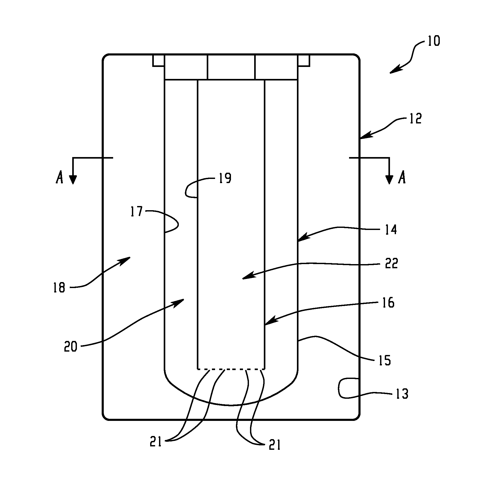
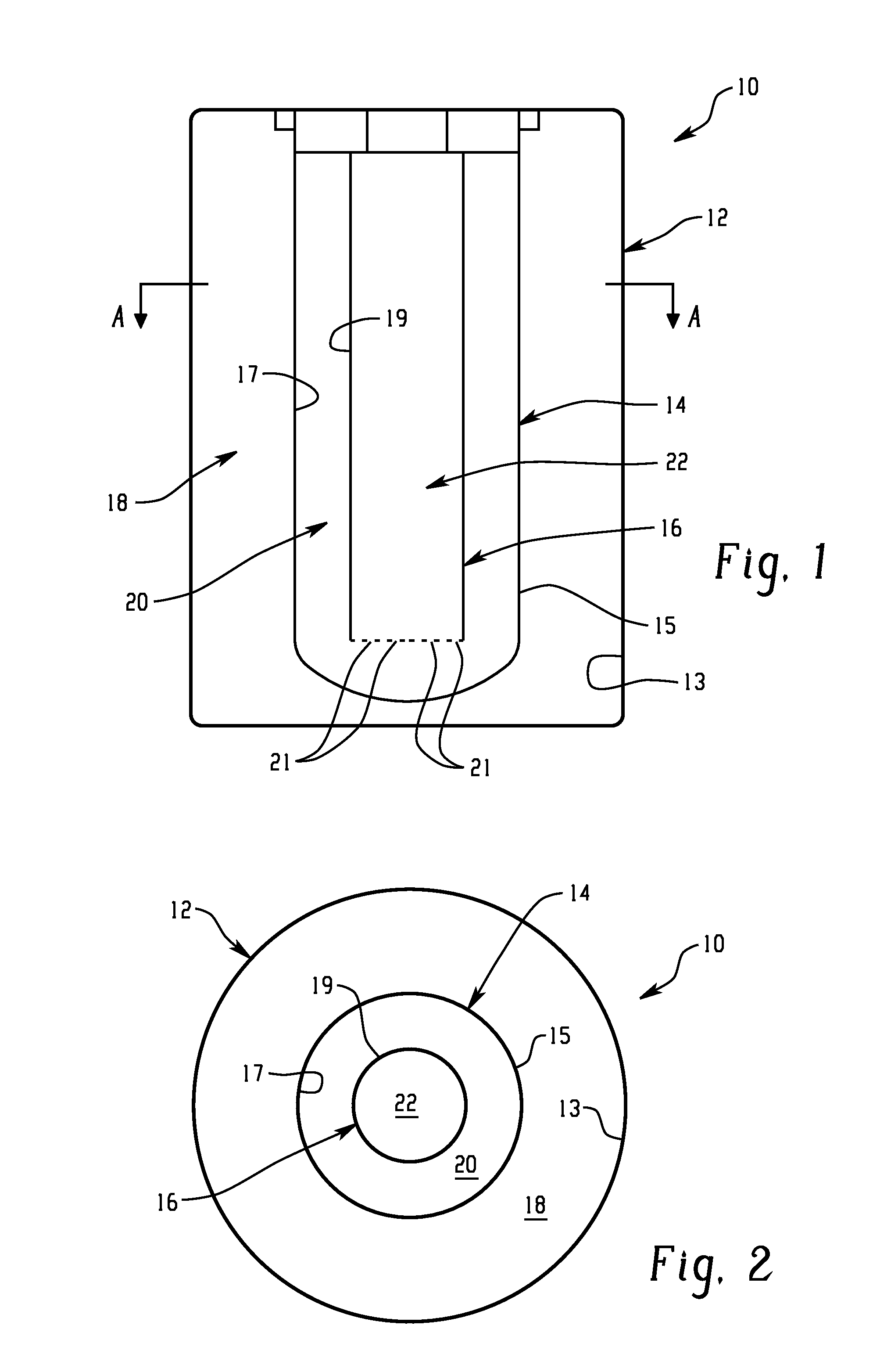
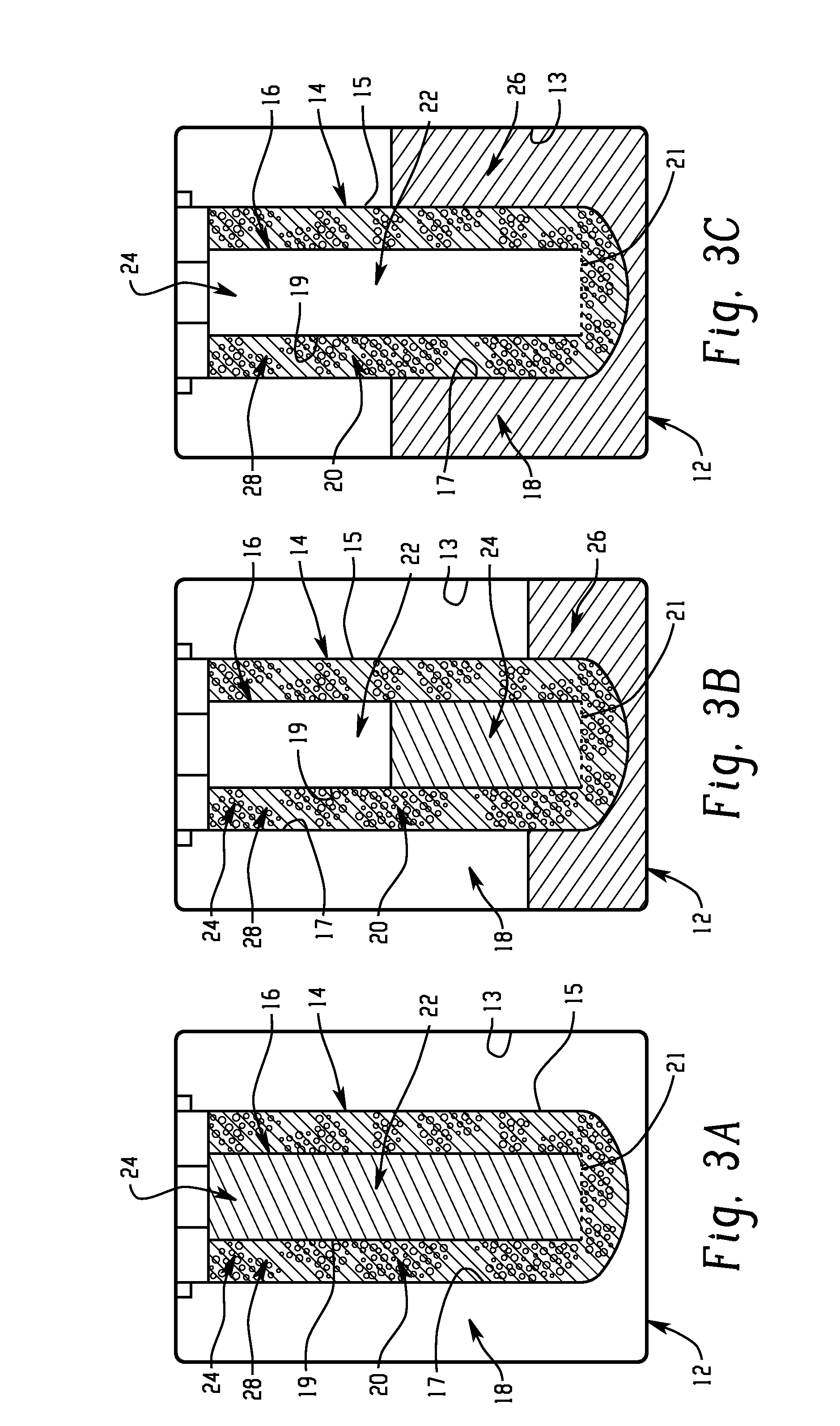
[0053]A Reference Cell (A) was prepared and contained 248 grams of cathodic (positive electrode) material impregnated with 115 grams of molten salt on assembly so that the level of the molten salt is above the level of the solid positive electrode material. The positive electrode is contained within a beta alumina tube with a central nickel current collector fitted with a thin porous membrane along its length. This assembly is contained within a steel cell case so that the space between the assembly and the inside of the cell case is the sodium electrode or anode.

[0054]A Test Cell (B) in accord with an embodiment of the invention was also prepared. Cell B was prepared in the same manner and using the same components as Cell A, with the exceptions as noted here. The Test Cell B was fitted with a larger porous membrane spacer and filled to the same electrode height with 230 grams of electrode material and 130 grams of molten salt, the excess amount of molten salt over that used in Ref...

example 2

[0058]For this Example, Reference Cell C was prepared in the same manner as Cell A in Example 1, but having larger physical dimensions and configuration, and following the same steps. Cell C has a nickel metal current collector in the form of two lengths of 4 mm diameter nickel wire disposed within the cell. Cell C contained 1274 grams of positive electrode material fully impregnated with 567 grams of molten salt electrolyte, i.e. the level of molten salt electrolyte was at least as much as or exceeded the solid electrode material level in the positive electrode chamber or second region.

[0059]Test Cell D was prepared in the same manner as Reference Cell C, except Test Cell D includes a current collector that is a hollow nickel tube as opposed to nickel wire as used in Cell C. The hollow nickel tube is 20 millimeters in diameter. The Test Cell (D) is filled with 1250 grams of positive electrode material fully impregnated with 640 grams of molten salt electrolyte. The hollow nickel tu...


PUM

PropertyMeasurementUnit
volumeaaaaaaaaaa
axial lengthaaaaaaaaaa

Abstract

An energy storage device is provided that includes a reservoir in operative communication with a positive electrode such that the positive electrode remains fully flooded, even at the top of the charge cycle. The device more particularly includes a housing receiving therein, in a coaxial manner, an ion conducting member, and a current collector member received coaxially within the ion conducting member. In this device, a first region is provided in the space between the housing and the ion conducting member and a second region is provided in the space between the ion conducting member and the current collector member. The interior of the current collector member defines a reservoir having a certain volume at least equal to the volume of the void space created in the second region during charging of the device.

Description

BACKGROUND OF THE DISCLOSURE[0001]1. Technical Field[0002]The invention includes embodiments that relate to an energy storage device. More particularly, the invention includes embodiments that relate to an energy storage device wherein the positive electrode is fully flooded even at the top of charge.[0003]2. Discussion of Art[0004]Metal chloride batteries with molten sodium anode and beta-alumina solid electrolyte are employed for energy storage applications. The energy storage application may include mobile applications due to the metal chloride battery's high energy density and long cycle life. Such energy storage devices include a sodium negative (anode) electrode separated from the positive (cathode) electrode by a sodium ion conducting ceramic beta-alumina structure or material. A secondary electrolyte, for example molten salt sodium tetrachloro aluminate, is present in the positive electrode to transmit sodium ions between the reaction sites in the positive electrode and the ...

Claims


Application Information

Patent Timeline
Patent Type & Authority Applications(United States)
IPC IPC(8): H01M10/39
CPCH01M2300/0048H01M10/399Y02E60/10Y02P70/50
Inventor GALLOWAY, ROBERT CHRISTIE
Owner GENERAL ELECTRIC CO
Why Eureka
Try Eureka