
Imaging-guided anesthesia injection systems and methods

a technology of anesthesia and injection system, applied in the field of injection and/or aspiration device, systems and methods, can solve the problems of reducing affecting so as to improve the chance of infection, improve the accuracy of injection, and improve the effect of accuracy

Inactive Publication Date: 2013-02-14
CARTICEPT MEDICAL
View PDF4 Cites 71 Cited by
  • Summary
  • Abstract
  • Description
  • Claims
  • Application Information

AI Technical Summary

Benefits of technology

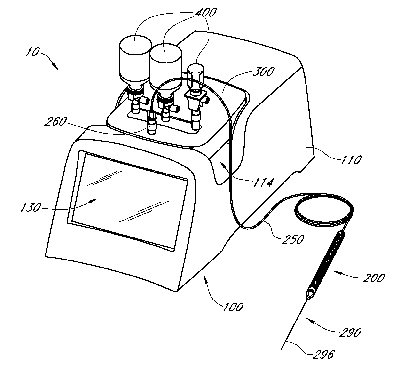
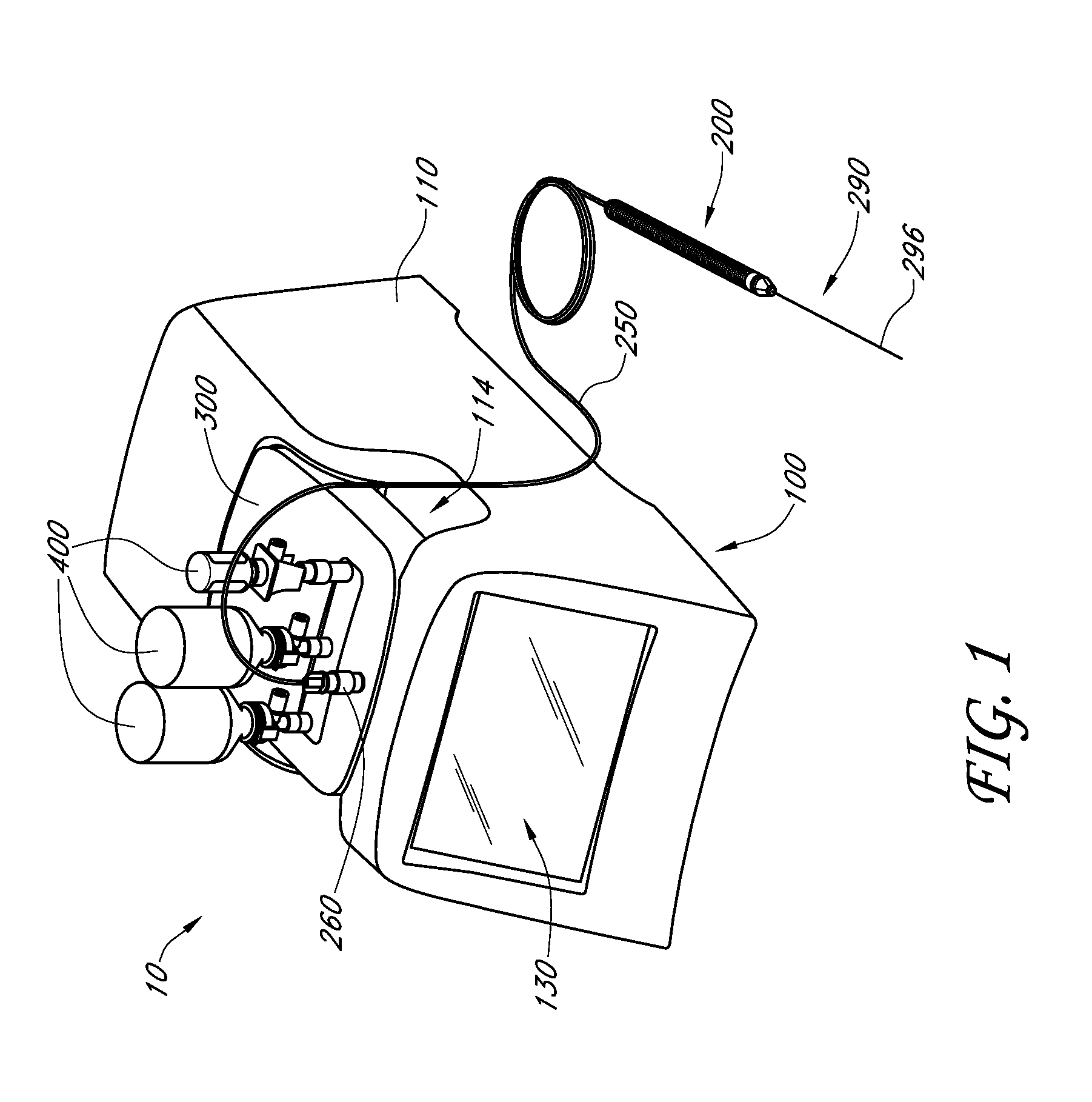
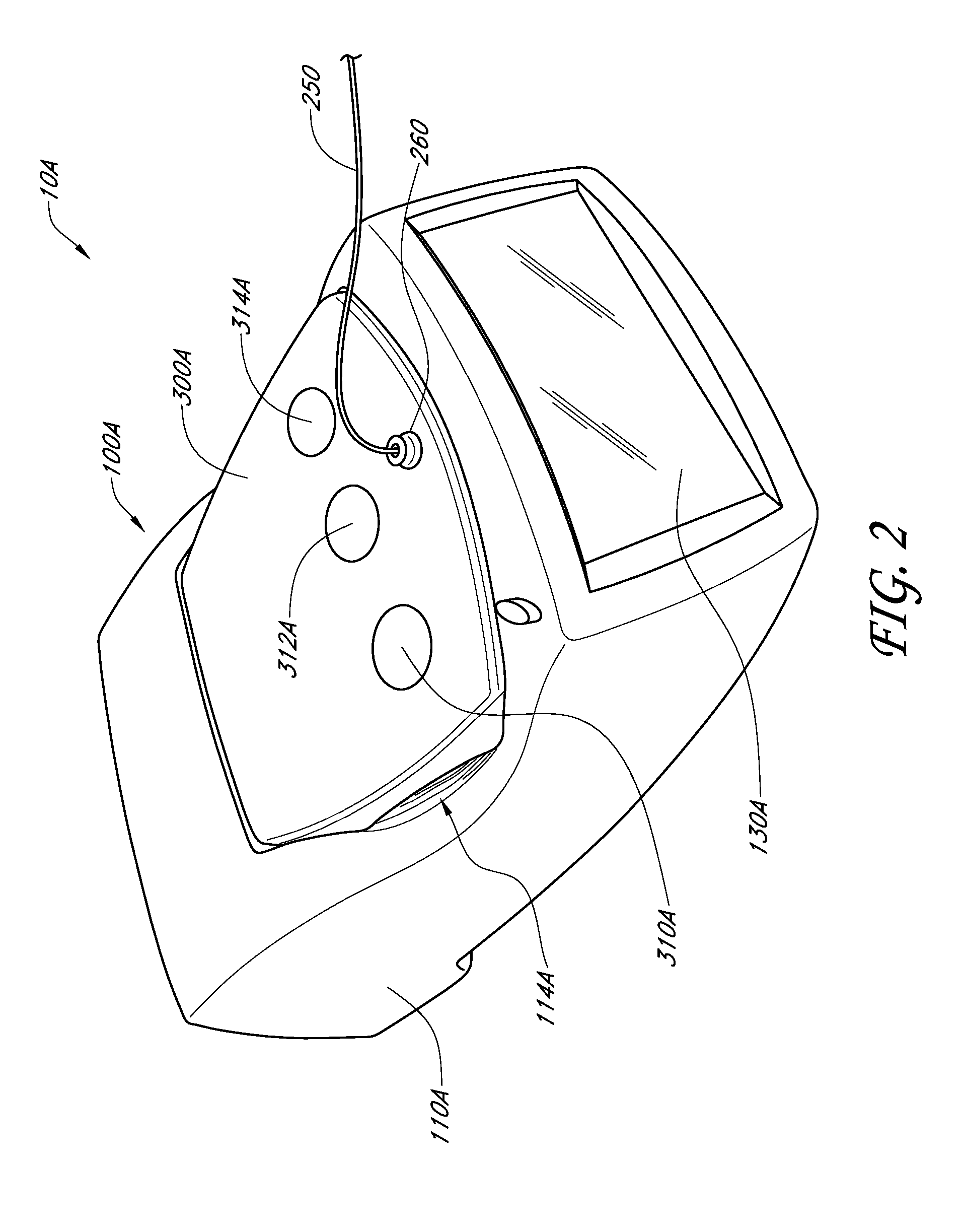
The patent describes an imaging-guided injection system that delivers anesthetic to a specific part of a patient's body. The system includes a fluid delivery module with a container for the anesthetic, a reservoir and a conduit for transferring the anesthetic from the container to the patient. The system also includes a motor to help move the anesthetic through the conduit and a controller to regulate the delivery of the anesthetic. The system can also be in communication with an imaging device to help guide the needle to the target area. The technical effect is a safer and more precise method for delivering anesthetic to a specific location in a patient's body.

Problems solved by technology

Although anesthetics can provide significant pain relief and offer many advantages and other benefits relating to surgical and / or other medical procedures, it still carries a risk of injury and other complications, such as, for example, inadvertent or unintended nerve damage and adverse effects resulting from a failure to properly locate targeted nerve tissue.
For example, studies have shown that conventional needles miss the target location quite frequently.
Further, certain medications, such as steroids, break down connective tissue and cause other tissue damage.
Therefore, when such medications or other formulations are not precisely delivered to the target intra-articular location, adverse tissue damage can occur to one or more anatomical locations of patients.
This can complicate the process for the physician or other person performing the procedure and breaks the sterile fluid path, thereby increasing the chance for infection.
In addition, the process can prove to be uncomfortable and painful to the patient.

Method used


Image

  • Imaging-guided anesthesia injection systems and methods
  • Imaging-guided anesthesia injection systems and methods
  • Imaging-guided anesthesia injection systems and methods

Examples


Embodiment Construction

[0184]In some embodiments, regional, peripheral or local anesthesia (e.g., a nerve block) involves the application of one or more local anesthetic agents or anesthetics to or near nerves (e.g., individual nerves, nerve bundles, other nerve tissue, etc.). As used herein, the term anesthetic is a broad term and includes, without limitation, any pharmaceutical, medicament, formulation and / or any other fluid, substance or material that causes anesthesia or a loss (e.g., reversible or permanent loss) of sensation. Anesthetics include, but are not limited to, local or regional anesthetics, analgesics and / or other painkillers or pain relieving materials, medicaments, materials and / or substances (e.g., alcohol, phenol, etc.) that at least partially destroy nerve tissue and / or the like. The terms anesthetic, anesthetic agent, nerve block and the like are used interchangeably herein. Anesthetics can include pharmaceuticals and / or formulations or combinations thereof. Further, anesthetics can ...


PUM


Abstract

Devices and systems for injecting fluids, such as anesthetics, to or near nerve tissue or other targeted anatomical location are disclosed herein. A conduit is generally configured to place the fluid delivery module in fluid communication with a needle that is configured to be inserted into the patient's anatomy. One or more medicaments (e.g., anesthetics) and / or other materials contained within containers (e.g., vials) that are secured to the injection system can be selectively delivered into an anatomy through the needle. Nerve stimulation and / or imaging technologies (e.g., ultrasound) can be used to locate a targeted anatomical location. Aspiration can be used to confirm needle location. An overlay on the imaging display can include, in addition to real-time imaging data, data and other information relating to back pressure at or near the needle tip, volumes or other amounts of fluids delivered by and remaining within the system, stimulation level and / or the like.

Description

RELATED APPLICATIONS AND INCORPORATION BY REFERENCE[0001]This is a continuation-in-part of U.S. patent application Ser. No. 12 / 823,004, filed Jun. 24, 2010 and published on Jan. 27, 2011 as U.S. Publication No. 2011 / 0021905, which is a continuation-in part of U.S. patent application Ser. No. 12 / 340,595, filed Dec. 19, 2008 and issued Aug. 23, 2011 as U.S. Pat. No. 8,002,736, which claims priority benefit under 35 U.S.C. §119(e) of U.S. Provisional Patent Application No. 61 / 016,395, filed Dec. 21, 2007, the entireties of all of which are hereby incorporated by reference and made a part of the present specification. This application also claims priority benefit under 35 U.S.C. §119(e) of U.S. Provisional Patent Applicant Nos. 61 / 551,760, filed Oct. 26, 2011, and 61 / 618,507, filed Mar. 30, 2012, the entireties of both of which are also hereby incorporated by reference herein and made a part of the present specification.BACKGROUND[0002]1. Field[0003]This application relates generally to...

Claims


Application Information

Patent Timeline
Patent Type & Authority Applications(United States)
IPC IPC(8): A61M5/31A61N1/05A61B8/00
CPCA61B8/00A61N1/3605A61M1/0039A61M5/20A61N1/0502A61M5/1408A61M5/142A61M5/14216A61M5/1452A61M5/162A61M5/16827A61M5/19A61B5/4839A61B2017/3413A61B2019/5276A61M2039/242A61M2039/246A61M2202/0241A61M2205/505A61M2209/084A61B8/461A61B8/467A61B8/464A61B8/465A61B2090/378A61M5/2066A61M1/76
Inventor PATRICK, TIMOTHYKNOSTMAN, RICHARDAXELROD, MICHAELRAMEY, CARRIBETH
Owner CARTICEPT MEDICAL
Learn More