
Mitigation of Radiation Induced Attenuation

a radiation-induced attenuation and radiation-induced attenuation technology, applied in the field of optical fiber distributed temperature systems, can solve the problems of radiation-induced attenuation in silica optical fibers, degrade the performance of optical sensors and communication systems, and lose optical signals

Active Publication Date: 2013-02-21
SENSORTRAN
View PDF4 Cites 6 Cited by
  • Summary
  • Abstract
  • Description
  • Claims
  • Application Information

AI Technical Summary

Benefits of technology

This patent describes a way to measure temperatures in optical fibers using a multi-wavelength system. By using photo bleaching, the system can measure the impact of radiation on the fiber and reduce the effect of attenuation. This helps to get more accurate temperature readings during system operation.

Problems solved by technology

This radiation-induced attenuation (or RIA) causes optical signal loss that degrades performance of optical sensor and communication systems.
Radiation induced attenuation in silica optical fibers is typically due to the presence of glass structural defects such as non bridging oxygen centers, alkali electron centers, and lattice vacancies in the silica network.
The more complex glass network formed with the addition of these dopants leads to a higher incidence of structural defects, such that these dopants are considered radiation-sensitizing agents.
Despite this high purity processing, however, these fibers still exhibit some radiation sensitivity, albeit at low levels when compared to conventional optical fibers.
However for other types of systems, such as optical sensing systems, even slight signal power loss can lead to significant measurement errors.
In some high sensitivity interferometric sensors, such as interferometric fiber optic gyroscopes (IFOGs) used in guidance systems, transient signal loss can affect the sensor scale factor and random noise performance.
This becomes especially problematic for such sensors to maintain performance when operating in hostile nuclear environments.
These approaches can be fairly effective but result in very expensive optical fibers.

Method used


Image

  • Mitigation of Radiation Induced Attenuation
  • Mitigation of Radiation Induced Attenuation
  • Mitigation of Radiation Induced Attenuation

Examples


Embodiment Construction

[0029]Although certain embodiments and their advantages have been described herein in detail, it should be understood that various changes, substitutions and alterations can be made without departing from the spirit and scope as defined by the appended claims. Moreover, the scope is not intended to be limited to the particular embodiments of the processes, machines, manufactures, means, methods and steps described herein. As a person of ordinary skill in the art will readily appreciate from this disclosure, other processes, machines, manufactures, means, methods, or steps, presently existing or later to be developed that perform substantially the same function or achieve substantially the same result as the corresponding embodiments described herein may be utilized. Accordingly, the appended claims are intended to include within their scope such processes, machines, manufactures, means, methods or steps.

[0030]The classical way to measure distributed temperature using Raman scatterin...


PUM

PropertyMeasurementUnit
Wavelengthaaaaaaaaaa

Abstract

A DTS system resistant to radiation induced attenuation losses during the service life of an installation at both low and high temperatures using matched multi-wavelength distributed temperature sensing automatic calibration technology in combination with designed Pure Silica Core (PSC) optical fibers and an in process photo bleaching method provided by the light sources of the distributed temperature sensing system.

Description

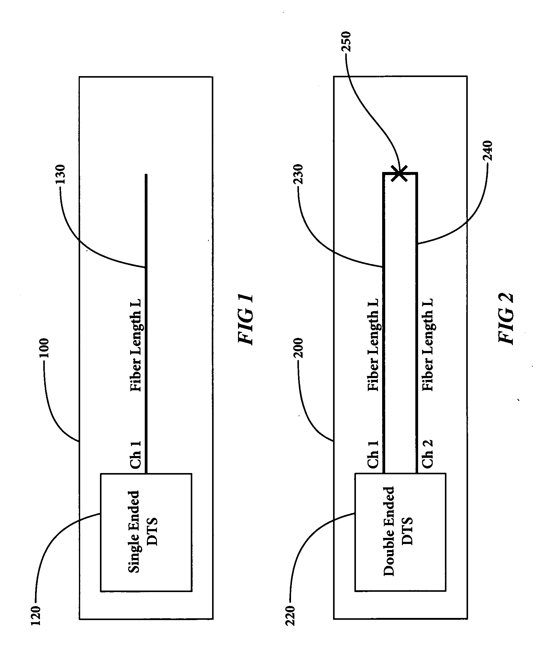
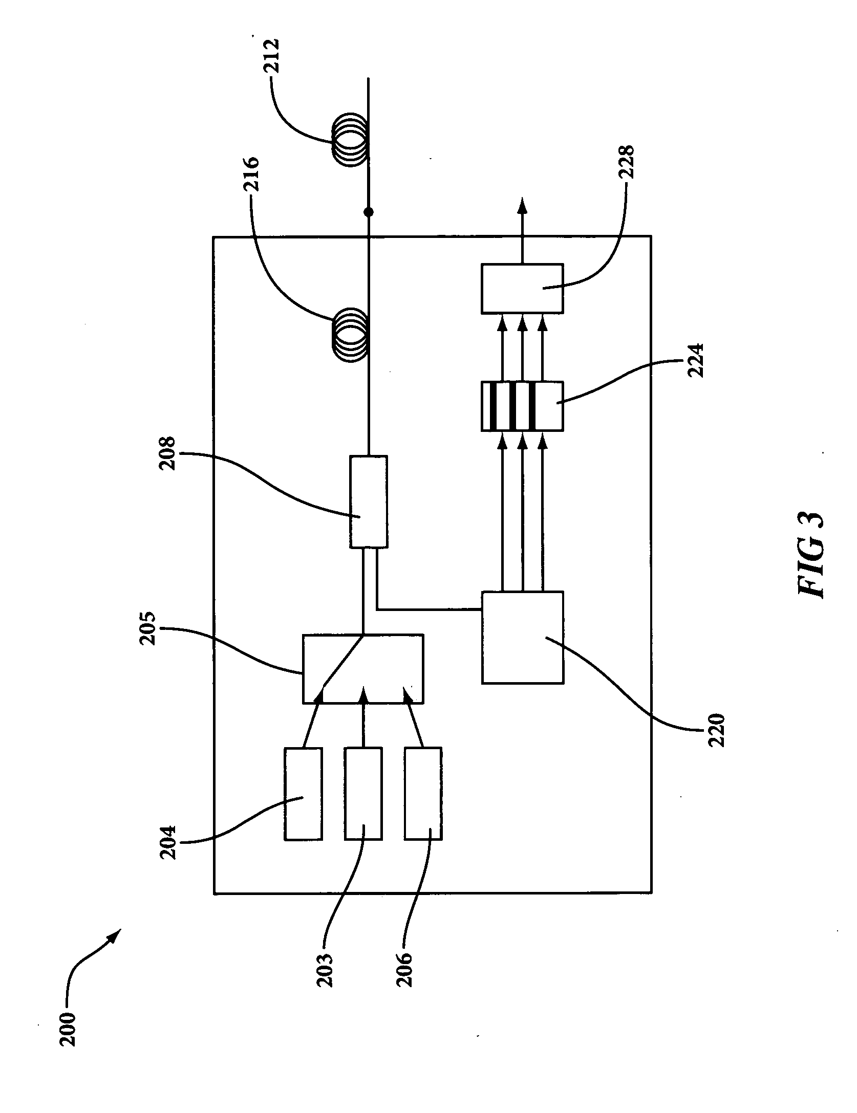
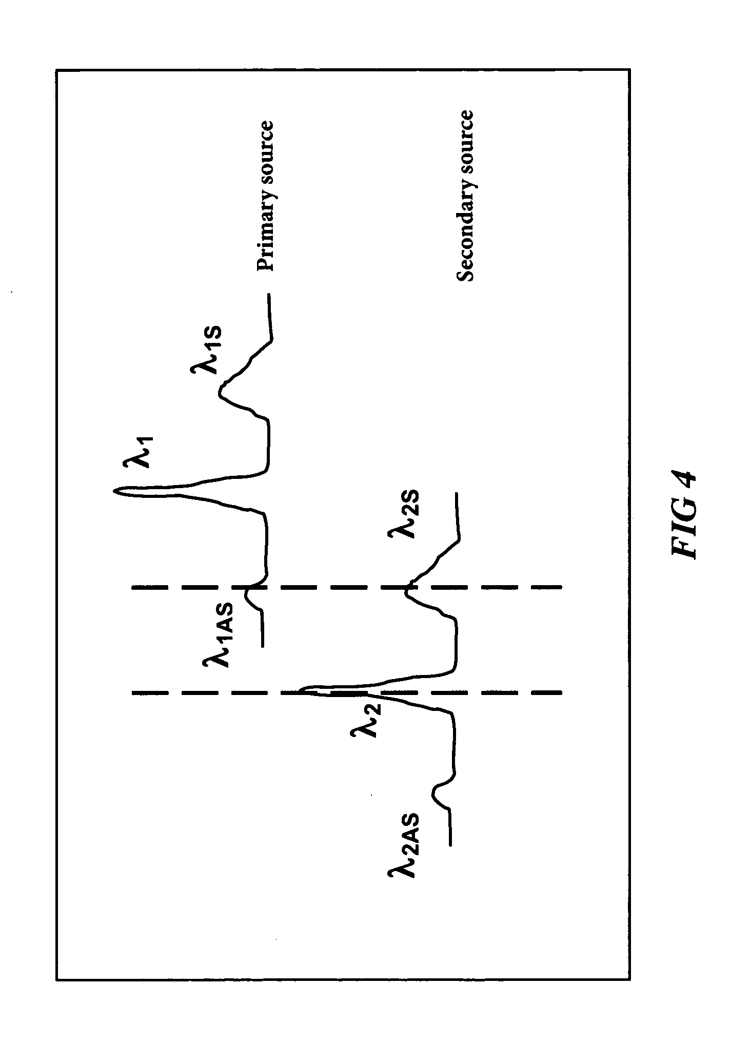
BACKGROUND AND FIELD OF THE DISCLOSURE[0001]1. Field[0002]This description relates to the use of optical fiber distributed temperature systems used in ionizing radiation environments and particularly to the use of in process photo bleaching of optical fibers in combination with selected multi wavelength DTS technology.[0003]2. Background[0004]Optical signals propagating through fibers experience induced attenuation or “darkening” when the fiber is exposed to ionizing radiation. This radiation-induced attenuation (or RIA) causes optical signal loss that degrades performance of optical sensor and communication systems. These radiation-induced losses are both transient and permanent in common telecommunications-grade optical fibers.[0005]Despite this issue optical fibers are often of interest in radiation environments. Compared to copper cables, fiber optic systems have many advantages, including good electromagnetic immunity and chemical stability, low weight and compactness, good rel...

Claims


Application Information

Patent Timeline
IPC IPC(8): D06L3/14D06L4/70
CPCG01K11/32
Inventor JAASKELAINEN, MIKKO
Owner SENSORTRAN
Learn More