Condenser with capillary cooling device

a cooling device and condenser technology, applied in lighting and heating apparatus, heating types, applications, etc., can solve the problems of low heat exchange efficiency, low thermal conductivity of air, and low heat sensibleness of conventional air-cooling condensers, so as to increase the thermal efficiency of the condenser

Inactive Publication Date: 2013-02-21
HONG JOUNG WEN
View PDF0 Cites 11 Cited by
  • Summary
  • Abstract
  • Description
  • Claims
  • Application Information

AI Technical Summary

Benefits of technology

[0006]The present invention relates to a condenser with a capillary cooling device, comprising a plurality of fins, a water reservoir, and a plurality of capillary water absorption layers. The plurality of fins is provided with wick structures on their surfaces thereof, respectively. The water reservoir is configured under the plurality of fins, and includes a water inlet pipe for supplying water into the water reservoir. The plurality of capillary water absorption layers is connected, respectively and correspondingly, at their upper sections, to the wick structures of the plurality of fins, and the plurality of capillary water absorption layers has its lower sections extended and submerged in the water of the water reservoir. As such, according to the present invention, capillarity and the characteristic of the plurality of capillary water absorption layers are utilized such that appropriate water moisturizes the fins having the wick structures. Moreover, a great amount of heat can be extracted from the fins when the water evaporates and a phase change occurs, so as to increase the thermal efficiency of the condenser.

Problems solved by technology

However, it is known that the conventional air-cooling condenser has a rather low thermal efficiency.
Further, the air, as employed in air-cooling condensers, has a low thermal conductivity in terms of sensible heat.
As such, the thermal efficiency for heat exchange is quite limited.
Moreover, in recent years, as influenced by greenhouse effect, global climate changes abnormally.
Hotter temperatures increase the demand for more air conditioning, and also cause the cooling efficiency of the air-cooling condenser to become much lower.
Since the resultant larger air-cooling condensers, as a whole, occupy more space and consume more energy, obviously the conventional air-cooling condensers are unsatisfactory.

Method used


Image

  • Condenser with capillary cooling device
  • Condenser with capillary cooling device
  • Condenser with capillary cooling device

Examples


Embodiment Construction

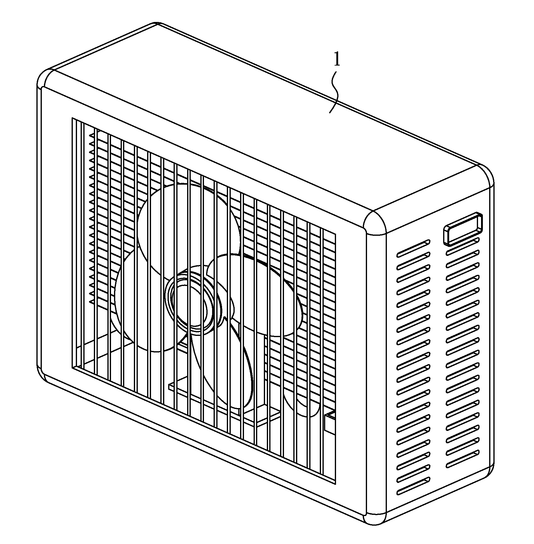
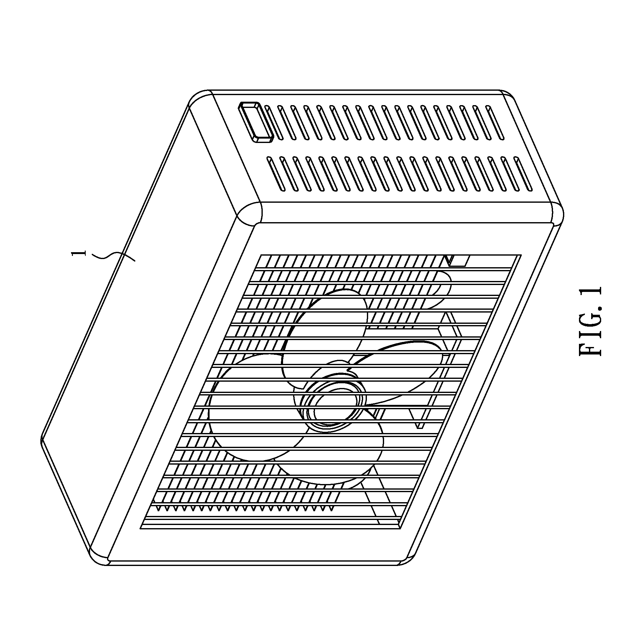
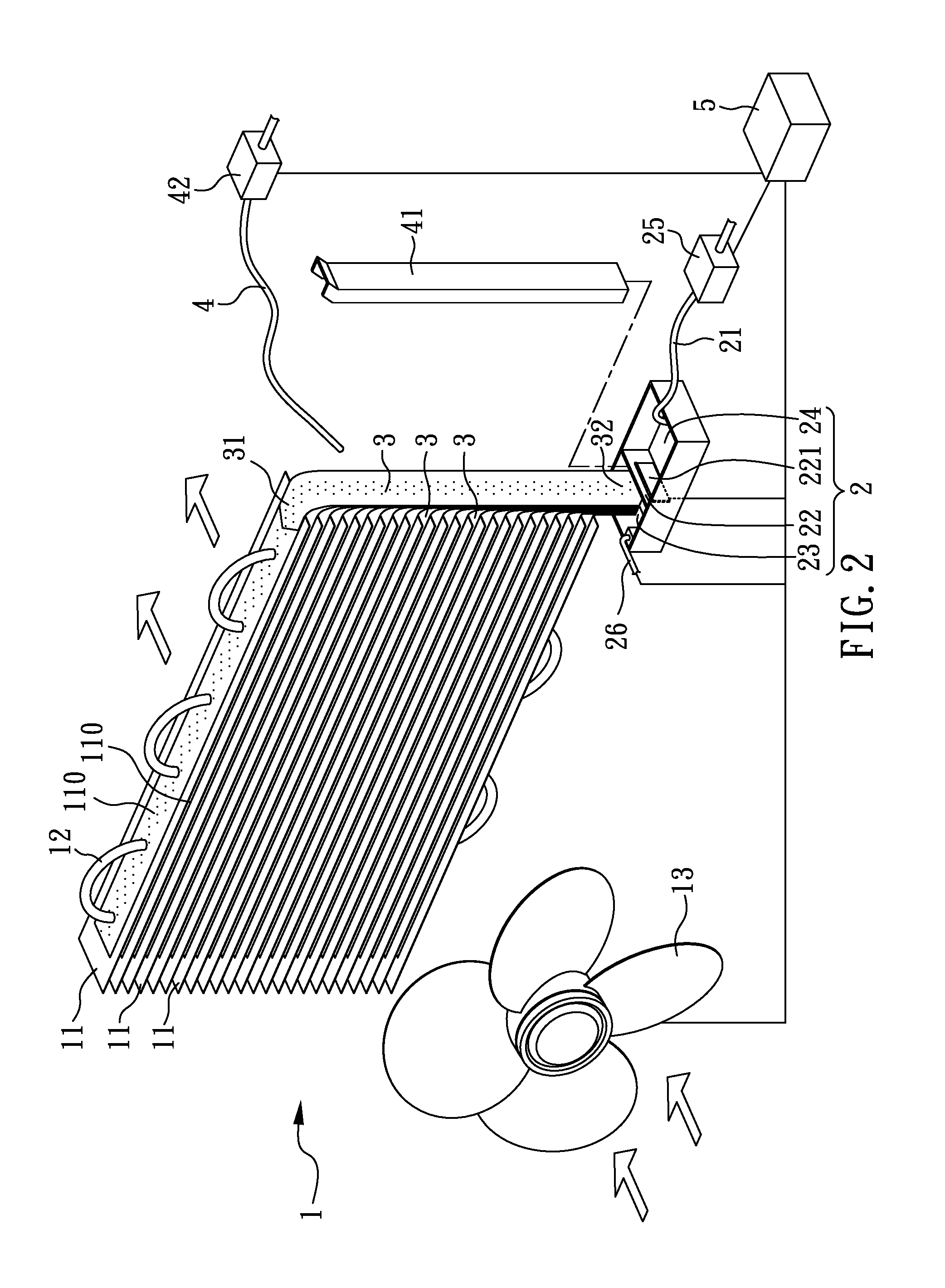
[0018]Referring to FIG. 1, a perspective view illustrating a condenser with a capillary cooling device according to a first embodiment of the present invention; and to FIG. 2, an exploded view illustrating an internal structure of a condenser according to the first embodiment of the present invention, a condenser 1 comprises a plurality of fins 11, a refrigerant coil tube 12, a water reservoir 2, a plurality of capillary water absorption layers 3, a pre-wet water pipe 4, a fan 13, and a controller 5. The controller 5 is arranged inside a housing of the condenser 1, and is electrically connected with a solenoid 42, a valve 221, a check valve 25, a water-level sensor 26, and a fan 13.

[0019]As shown in FIG. 2, the refrigerant coil tube 12 is inserted into and among the plurality of fins 11 horizontally arrayed. And at least one side of each fin of the plurality of fins 11 is provided with a wick structure 110. In the present embodiment, each capillary water absorption layer of the plur...


PUM


Abstract

A condenser with capillarity cooling devices provides a condenser that has a plurality of cooling fins with a wick structure and a plurality of capillary water absorption layers of which the lower section is submerged in the water of a water reservoir provided underneath. Through capillarity and the characteristic of the capillary water absorption layers, water will be brought upward to moisturize the fins. When the water evaporates, a great amount of heat will be extracted from the fins, so as to increase the thermal efficiency of the condenser. Further, a pre-wetting water pipe is included, so that when an air conditioner is switched on and the condenser is started, the pre-wetting water pipe moisturizes the capillary water absorption layers immediately, and such moisture extends to the overall wick structures of fins. This will make evaporation take place instantly and thermal efficiency of condenser is increased.

Description

BACKGROUND OF THE INVENTION[0001]1. Field of the Invention[0002]The present invention relates to a condenser with a capillary cooling device, and more particularly, to a condenser adapted for a cooling apparatus of high thermal efficiency.[0003]2. Description of Related Art[0004]In the condenser of a conventional air conditioning system, refrigerant turns into a high-pressure and high-temperature state after having been compressed by a compressor. The refrigerant then passes through a coil tube, where air is employed as a cooling medium, such that a cooling effect can be achieved by airflow. However, it is known that the conventional air-cooling condenser has a rather low thermal efficiency.[0005]Further, the air, as employed in air-cooling condensers, has a low thermal conductivity in terms of sensible heat. As such, the thermal efficiency for heat exchange is quite limited. Moreover, in recent years, as influenced by greenhouse effect, global climate changes abnormally. The summer...

Claims


Application Information

Patent Timeline
Patent Type & Authority Applications(United States)
IPC IPC(8): F28D15/00
CPCF28F13/003F28D1/0477F28D5/00F25B39/04F28D2021/007F24F1/14F24F1/42F28F1/32
Inventor HONG, JOUNG-WEN
Owner HONG JOUNG WEN
Why Eureka
Try Eureka