Method for correcting electronic proximity effects using off-center scattering functions

a technology of scattering function and electronic proximity, applied in the field of electronic lithography, can solve the problems of poor efficiency of this model, model is not a good fit with reality,

Active Publication Date: 2013-02-21
COMMISSARIAT A LENERGIE ATOMIQUE ET AUX ENERGIES ALTERNATIVES +1
View PDF9 Cites 15 Cited by
  • Summary
  • Abstract
  • Description
  • Claims
  • Application Information

AI Technical Summary

Benefits of technology

[0023]In an embodiment of the invention in which a PSF comprising two gamma distribution functions is used, it has been possible to demonstrate a very significant improvement on the residual root mean square error which is 49% less than that observed with two centered Gaussians and 32% less than that observed with the improvement provided by Kamikubo.

Problems solved by technology

The efficiency of this model is, however, not good, notably for the distant effects which are dominated by backscattering.
One of the common features of the PSFs of the prior art is to use centered functions, that is to say, functions for which the maximum amplitude is located where the center of the electronic beam interacts with the target (for the sake of simplicity, this will hereinafter be referred to as at the center of the beam); now, this model is not a good fit with reality, notably in the application scenarios described above in which the proportion of backscattering is significant.

Method used


Image

  • Method for correcting electronic proximity effects using off-center scattering functions
  • Method for correcting electronic proximity effects using off-center scattering functions
  • Method for correcting electronic proximity effects using off-center scattering functions

Examples


Embodiment Construction

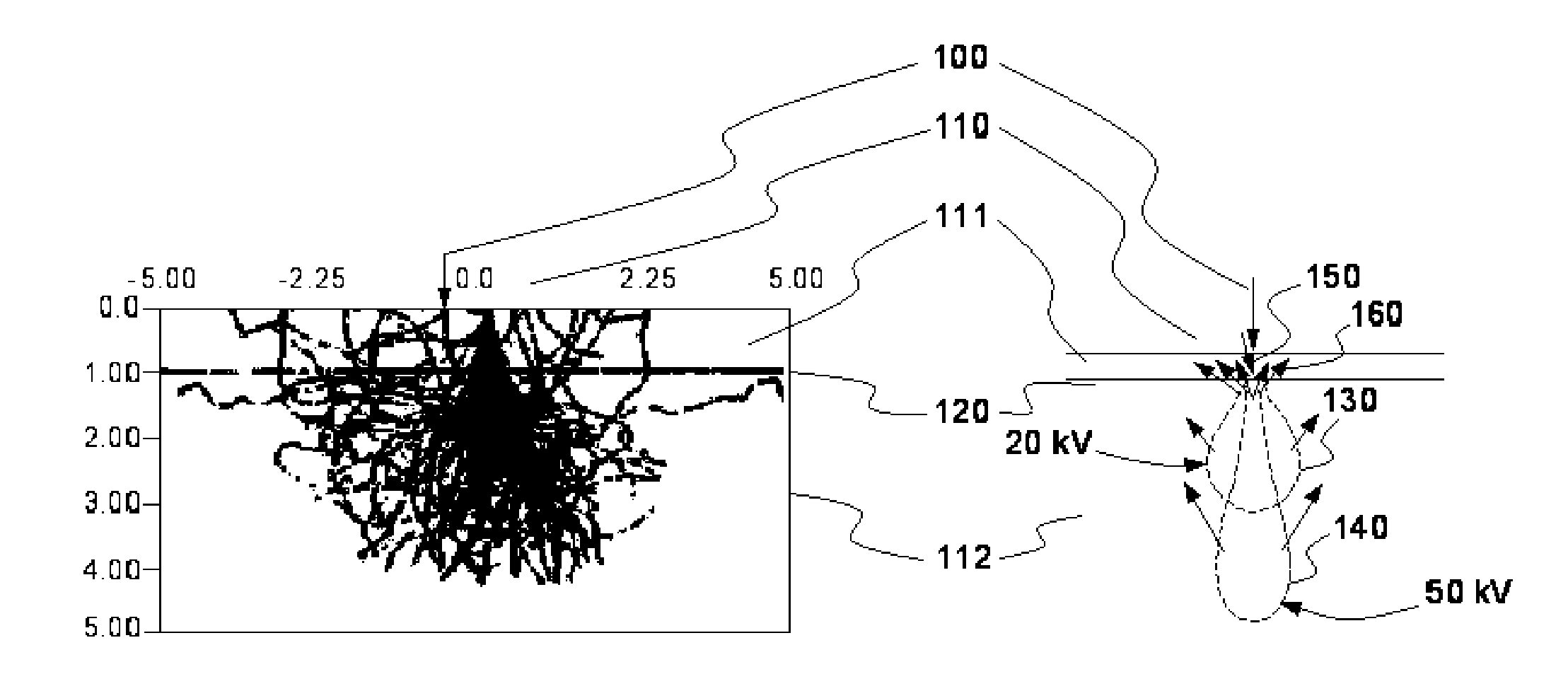
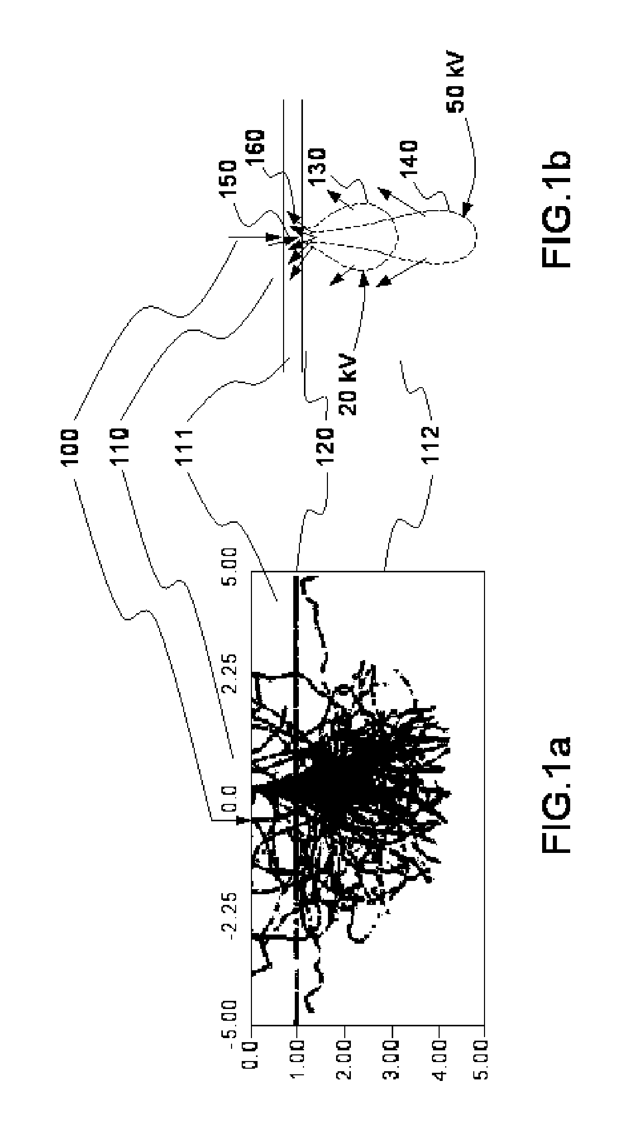
[0030]FIGS. 1a and 1b illustrate the effect of backscattering of the electrons.

[0031]FIG. 1a shows a vertical cross section of the trajectories of the electrons of a beam in a target 110 (a layer of resin 111 then in the substrate 112 delimited by the line 120). The random nature of the trajectories, which lends itself well to a modeling by Monte-Carlo simulation, can be observed. However, a simulation of this type is difficult to use in production because it does not allow for direct calculation with parameterized or tabulated functions.

[0032]In FIG. 1b, the two scattering effects resulting from the interactions of the electronic beam 100 with the target 110 have been modeled. Two scattering clouds 130, 140 are represented which correspond to acceleration voltages of 20 kV and 50 kV. The forward scattering is represented by the arrow 150 and the backscattering by the arrows 160. As can be seen, the higher the acceleration voltage, the deeper the cloud but the smaller the aperture o...


PUM


Abstract

A method for projecting an electron beam, used notably in direct or indirect writing lithography and in electronic microscopy. Proximity effects created by the forward and backward scattering of the electrons of the beam in interaction with the target must be corrected. For this, the convolution of a point spread function with the geometry of the target is conventionally used. At least one of the components of the point spread function has its maximum value not located on the center of the beam. Preferably, the maximum value is instead located on the backward scattering peak. Advantageously, the point spread function uses gamma distribution laws.

Description

CROSS-REFERENCE TO RELATED APPLICATIONS[0001]This application claims the benefit of French Patent Application No. 11-57338, filed on Aug. 16, 2011, the contents of which are incorporated herein by reference.BACKGROUND[0002]1. Field of the Invention[0003]The present invention applies notably to the field of electronic lithography for direct etching on a wafer or for fabricating masks. More generally, it applies to any field in which there is a need to model the interaction of an electron beam with a target, which is also the case in electronic microscopy, notably for the inspection of the wafers and of the masks.[0004]2. Description of the Related Art[0005]The interaction of an electron beam with a target is notably affected by a scattering of the electrons around the initial trajectory (forward scattering effect) and by a back-scattering effect. These effects, termed proximity effects, depend notably on the materials of the target and on its geometry. Whatever the reason for wanting...

Claims


Application Information

Patent Timeline
Patent Type & Authority Applications(United States)
IPC IPC(8): G21K5/00H01J37/26
CPCG03F7/2061H01J37/222H01J37/3174B82Y40/00H01J2237/31769B82Y10/00H01J2237/226H01J3/12H01J2229/563
Inventor SCHIAVONE, PATRICKFIGUEIRO, THIAGO
Owner COMMISSARIAT A LENERGIE ATOMIQUE ET AUX ENERGIES ALTERNATIVES
Why Eureka
Try Eureka