

Swing internal contact type planetary gear device and rotation drive device
a technology of rotating drive and gear device, which is applied in the direction of gearing, lifting equipment, transportation and packaging, etc., can solve the problem of device having a problem of oversized diameter
- Summary
- Abstract
- Description
- Claims
- Application Information
AI Technical Summary
Benefits of technology
Problems solved by technology
Method used
Image

Examples
first embodiment
1. First Embodiment
1-1. Structure of Swing Internal Contact Type Planetary Gear Device
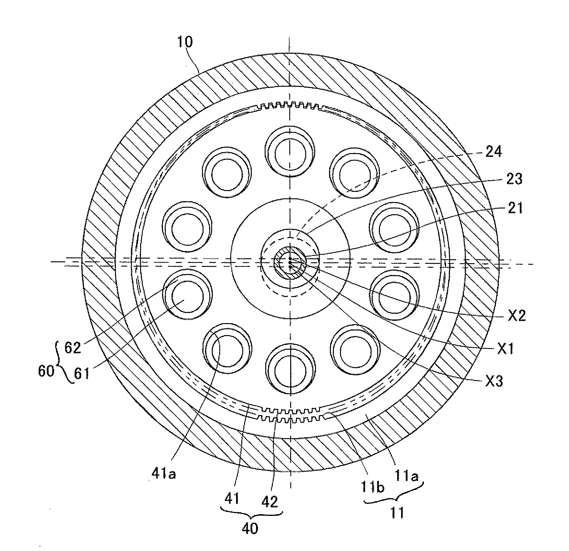
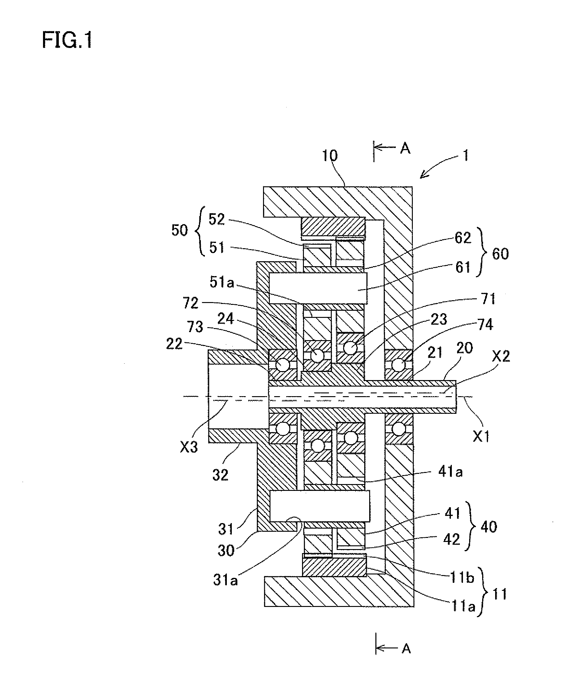
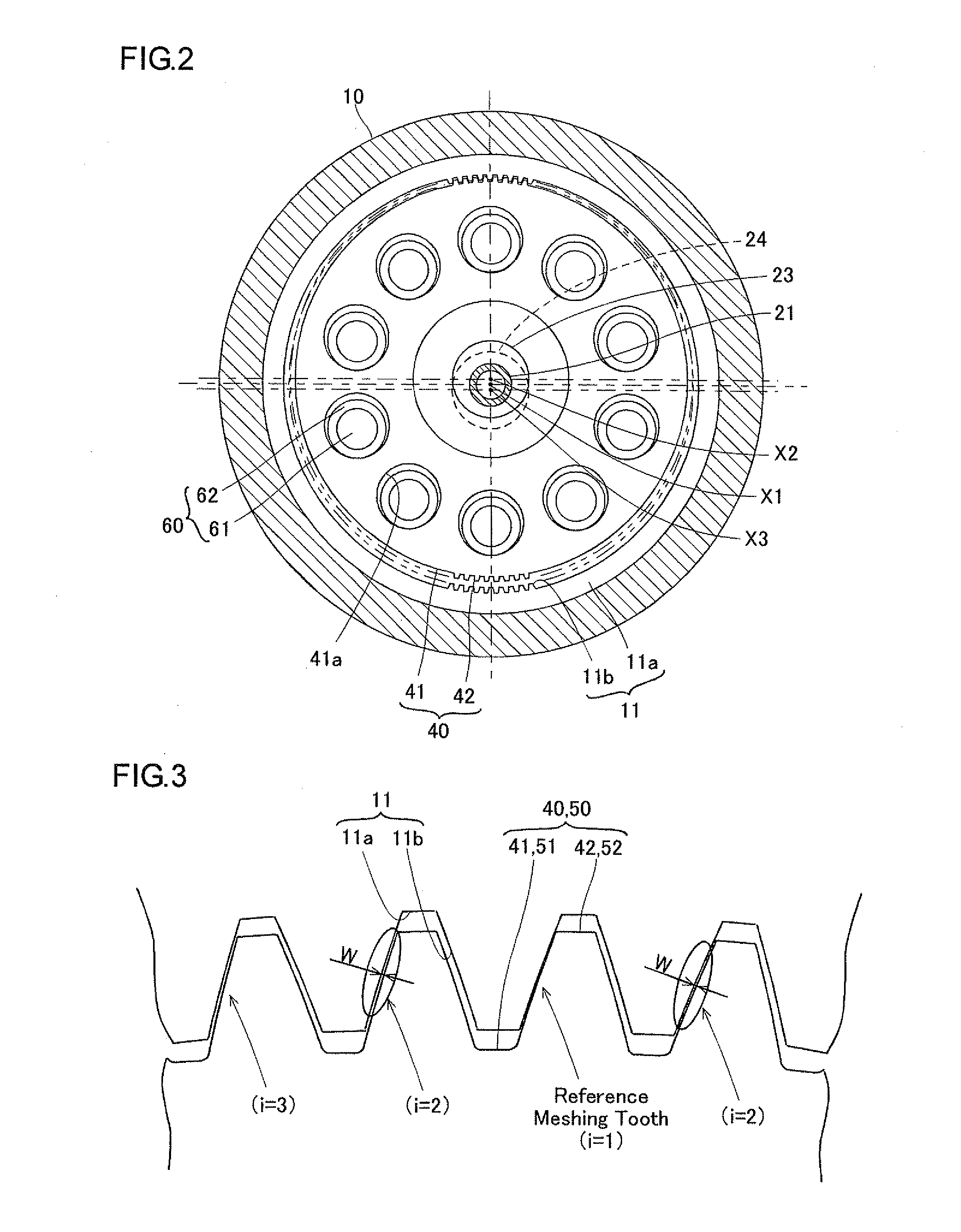
[0073]The structure of the swing internal contact type planetary gear device 1 of the embodiment will be explained hereinafter with reference to the attached drawings, FIG. 1 and FIG. 2. The swing internal contact type planetary gear 1 functions as a speed reduction gear device having an input shaft 20 and an output shaft 30 provided co-axially with the input shaft and transmits rotation of the input shaft 20 to the output shaft 30 by reducing the rotational speed of the input shaft. This speed reduction gear device can be also used as a speed increase gear device by reversing the input / output rotation between the input shaft 20 and the output shaft 30.
[0074]The swing internal contact type planetary gear device 1 is summarized by the device which includes an internally toothed gear wheel 11 formed at an inner circumferential surface of the housing 10 and the first external tooth 40 and the second e...
second embodiment
2. Second Embodiment
[0164]Next, a rotation driving device 100 using the swing internal contact type planetary gear device 101 will be explained with reference to FIGS. 12 and 13.
[0165]The rotation driving device 100 is structured by a motor 180 and the swing internal contact type planetary gear device 101. According to this structure, the rotation driving force of the motor 180 is transmitted to the swing internal contact type planetary gear device 101 to achieve speed reduction operation.
[0166]The motor 180 includes a cylindrically shaped rotor 181 and a cylindrically shaped stator 182 positioned opposite to the rotor 181 outwardly in a radial direction. The cylindrical rotor 181 includes, for example, a rotor yoke and a magnet. The stator 182 includes a stator core and a coil wound around the stator core.
[0167]The swing internal contact type planetary gear device 101 has basically the same structure as that of the swing internal contact type planetary gear device 1 except the feat...
third embodiment
3. Third Embodiment
[0185]Next, the rotation driving device 200 using the swing internal contact type planetary gear device 201 will be explained with reference to FIG. 14. The rotation driving device 200 includes a motor 180 the structure of which is the same as the motor in the second embodiment and a swing internal contact type planetary gear device 201, the structure of which is substantially the same as the swing internal contact type planetary gear device 1. The housing 210 of this embodiment also is the same structure as that of the housing 110 of the second embodiment. However, the input shaft 220 is different in structure from the input shaft 120 of the second embodiment. The explanation of this embodiment will only be made to the points different from the first and the second embodiments.
[0186]The input shaft 220 is formed by a base end portion 221 (right side in FIG. 14), a rotor fitting portion 222, a groove portion 223, a first eccentric body portion 224, a second eccent...
PUM
 Abstract
Description
Claims
Application Information