
Tape applicator

Active Publication Date: 2013-02-28
LAMUS ENTERPRISES
View PDF8 Cites 13 Cited by
  • Summary
  • Abstract
  • Description
  • Claims
  • Application Information

AI Technical Summary

Benefits of technology

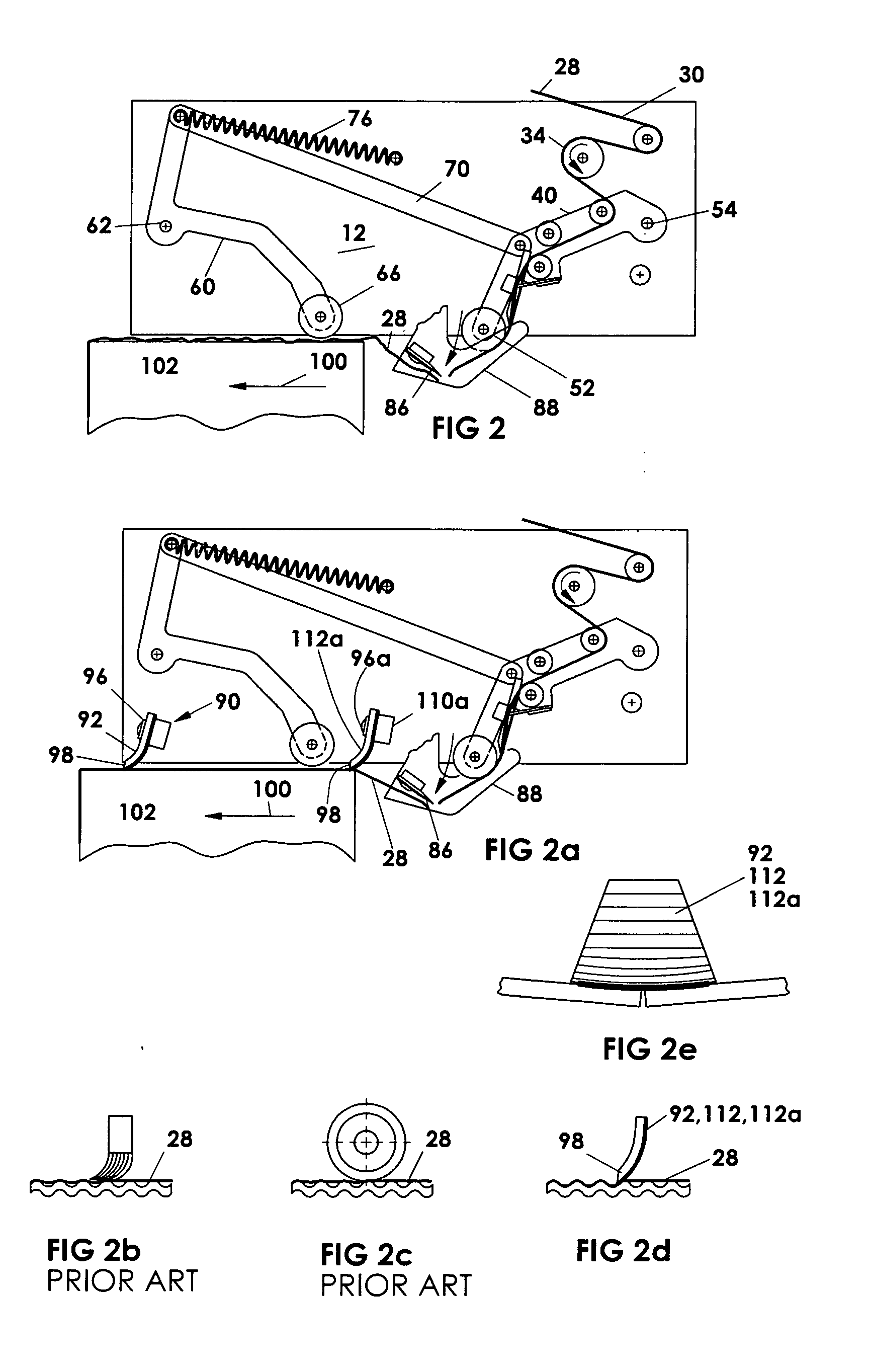
The present invention aims to provide improvements in carton taping, including social, safety, reliability, and performance. It proposes a system using a single or multiple flexible wiping elements to improve tape adhesion on soft, under-packed or uneven carton surfaces. This system also reduces tape cutting knife risks and adhesive and debris build-up, facilitates long or short tape tab application, and simplifies over-spinning of a large tape roll and locking of the tape roll to the mounting hub. Additionally, the invention includes a shaping pad, a deforming element, an exit roller, and a pressure surface to hold the tape against the exit roller. These features help to make the tape application process more effective and efficient.

Problems solved by technology

Common problems in carton taping include loosely wrinkled tape left on the taped carton; flagging at the rear corner; tape not making sufficient surface contact to adhere to the carton particularly in soft, under-packed or un-even surfaces carton conditions.
When the resisting tape tension increased or a light spring force setting is being used for soft carton, the tape will pull the front and the rear rollers away from the surface of the carton, reducing the application pressure or completely losing surface contact between the tape and the carton, with insufficient tape adhesion to the carton during the application process, the tape cut off with a sudden release of tension causing the tape to snap back with wrinkled, misaligned or crumpled tape placement on the carton which is being brush down by a brush further down the end of the tape applicator.
This wiper mounted on the front applicator arm aggravated the above-mentioned problem because the tape generated more friction around the end of the wiper that in many cases dragged the wiper away from the taping surface.
When a serrated blade is used the teeth of the serrated blade penetrate through the thickness of the tape, resulting in the tip of the teeth puncturing the tape at contact and wedging the tape to the bottom of the teeth, as a result, any adhesive or loose debris of tape from the cutting may wedged in between the bottom of the teeth, consolidated and slowly build up.
As a result it is common practice to provide an oil pad attached to the blade cover to lubricate the cutting blade to minimize the amount of build-up, however, it still requires periodically cleaning.
Otherwise it will affect the tape cutting causing production down-time.
Another problem with conventional tape applicators is related to holding and guiding the end of the tape in position for application to the leading end of a case or carton being taped.
This is not reliable especially when taping the bottom of a case or carton, the tape often falls off the application roller and misses the carton.
Many mechanical devises are being used to retain the leading portion of the tape to prevent the falling of the tape as well as forming the tape from both side or in the middle of the tape in order to make the tape more rigid and thereby hold its position relative to the surface of the application roller, those devises are complicated which makes tape threading difficult, most importantly, they are not effective when a short tab length application is required i.e. a short tab has a leading end of the tape that is not long enough to reach the surface of the application roller.
U.S. Pat. No. 5,725,721 provides an example of a device that can hold and expose the short leading end of the tape however, it does not provide a full surface support at the back of the tape to sufficiently presses the tape onto the carton surface and the tape will just smear the surface of the carton without adhesion so that the entire taping process is in effective.
In most cases, lacking full backing support of the short leading end of the tape causes the tape partially adhered onto the vertical surface of the carton, the corner of the carton may help to pull and advance the tape from up-stream to complete the taping process however, the taped carton is defective with insufficient adhesion of the front tab having the flaps loosely taped around the shoulder of the carton.
This method is not very effective as the changes in tape tension can create problems in tape adhesion and tape cutting.
Moving the one way clutch roller complicates the mounting of this roller and generally increases the time required to change between short and long front panel tabs.
Most importantly, adjusting the one way clutch roller can only affect a small amount of tape length adjustment.
All these locking devise are not sufficient to secure the tape roll.
As the tape roll reduces towards the end, less tape wound around the paper core which starts to loosened and deformed, consequently the leaf spring or knurled surface roller lose their gripping effect and the tape roll slides off the hub.

Method used


Image

  • Tape applicator
  • Tape applicator
  • Tape applicator

Examples


Embodiment Construction

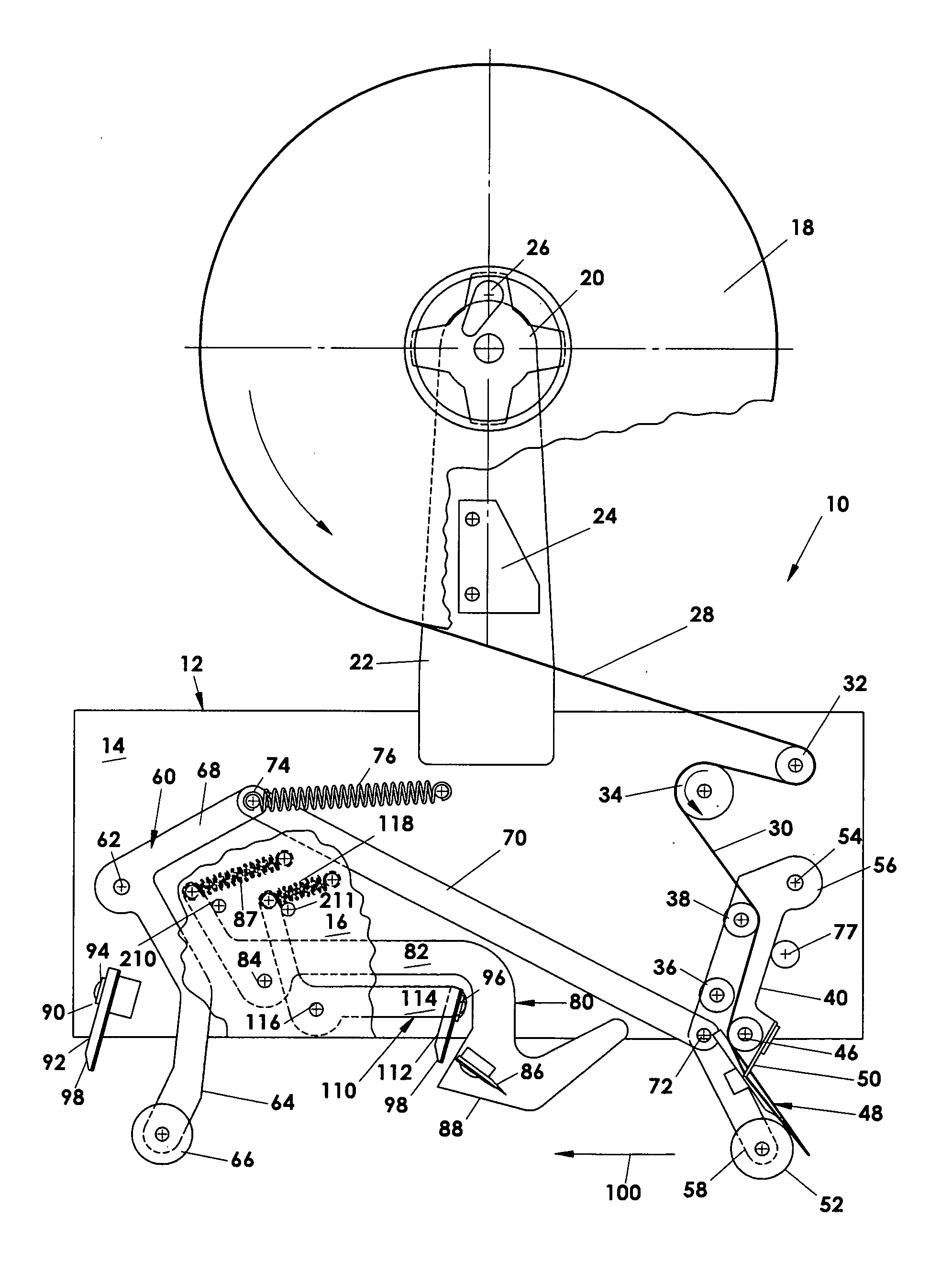
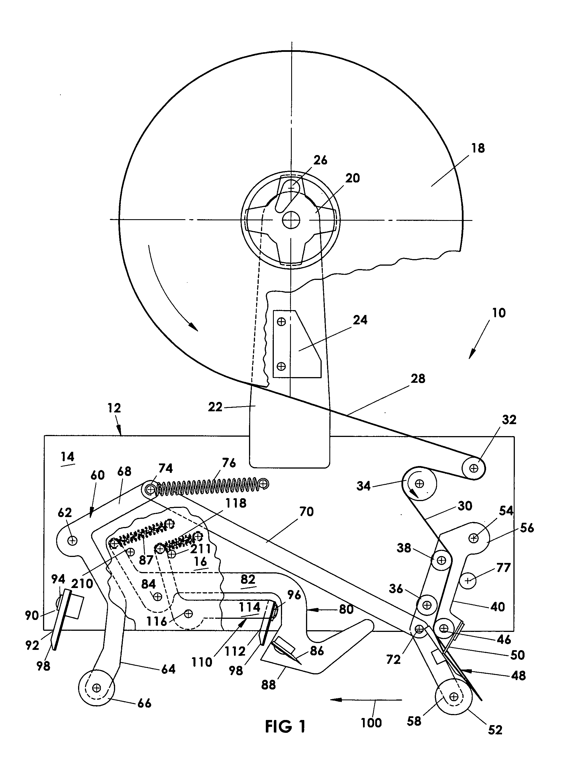
[0058]FIG. 1 shows the general view of a tape applicator 10 of the current invention having a base 12 formed by a pair of opposed substantially parallel walls 14 and 16 from which the various components of the applicator 10 are mounted. A tape roll 18 forming the supply of tape to be fed to the machine is mounted on a hub 20 which in turn is mounted on an arm 22 fixed to the wall 14. A braking system 24, which will be described in more detail with reference to FIGS. 7, 7a, 7b, 7c and 7d, is mounted on the tape support arm 22 and the hub 20 is provided with a locking system 26 which will be described in more detail with reference to FIGS. 8, 8a, and 8b.

[0059]The tape 28 follows along a tape path 30 by first passing over the guide roll 32 then the one-way clutch roller 34 mounted on the frame 14 and then over a selected one of the guide rolls 36 or 38 in the illustrated arrangement of FIG. 1 to selectively provide a long 42 (see FIG. 5a) or short 44 (see FIG. 5c) leading tab as will ...


PUM

PropertyMeasurementUnit
Lengthaaaaaaaaaa
Lengthaaaaaaaaaa
Angleaaaaaaaaaa

Abstract

An improved tape applicator for apply a tape to close a case or box is provided that uses a wiper system that better seals the tape to the box, provides an improved cut-off system wherein the action of the cut-off blade which partially cuts and then tears the tape is across the tape path at an improved angle. Also included is an improved system for adjusting tab length on the lead end of the case, providing a stiffened free end portion of the tape to engage an on-coming case, for controlling the rotation of large tape rolls by applying pressure to the side of a large roll and locking the tape roll to the mounting hub on the machine by penetrating the tape roll core with locking elements.

Description

FIELD OF INVENTION[0001]The present invention relates to a tape applicator for applying closure tapes to close cartons and incorporating improvements help to overcome or significantly reduce taping problems that have plagued the industry for years problems such as insufficient tape adhesion on under-filled boxes or cartons, tape cutting safety risk and deficiency and tape feeding issues.BACKGROUND OF THE PRESENT INVENTION[0002]Equipment for applying tape in a C-clip configuration are very well known and are commonplace in the literature and the industry A conventional taping machine uses a conveying system to advance the carton through the tape applicators positioned to apply a strip of tape from a roll of tape to the carton from the top, the bottom or the side with different speeds under different carton packaged conditions such as empty, over-filled or under-filled cartons. Such applicators generally apply a continuous ribbon of tape onto a leading face of a case or carton passing...

Claims


Application Information

Patent Timeline
IPC IPC(8): B32B37/12B32B38/10B32B38/18B32B37/10
CPCB65H35/0013Y10T156/17Y10T156/12B65H2801/81B65B51/067B65H35/0033
Inventor LAM, JOE AUGUSTINE S. T.
Owner LAMUS ENTERPRISES
Learn More