Modular jetting devices

a technology of modular jetting and jetting device, which is applied in the direction of valve operating means/releasing devices, mechanical equipment, conductive pattern formation, etc., can solve the problems of wear and friction, difficult disassembly and assembly of components of conventional jetting devices, and difficulty in cleaning conventional jetting devices. , to achieve the effect of improving flexibility and usability of jetting devices, reducing maintenance downtime, and convenient disassembly and assembly

Active Publication Date: 2013-02-28
NORDSON CORP
View PDF15 Cites 47 Cited by
  • Summary
  • Abstract
  • Description
  • Claims
  • Application Information

AI Technical Summary

Benefits of technology

[0028]The design architecture of the jetting devices of the various embodiments of the invention reduces maintenance downtime and improves flexibility and usability of a jetting device. Specifically, different component modules can be assembled based on application requirements. The modular design includes a wetted path segregated from the mechanical drive, which allows different mechanical drivers such as piezoelectric drive module, a pneumatic drive module, or an electromagnetic drive module to be used as different options. Thus, a drive module that is appropriate for the application and target sale price of the particular jetting device product model to the user can be selected. The modular design can also accommodate different fluid supply modules, again to optimize the jetting device for the application and target sale price to the user.
[0029]Due to the modularity provided the assembled components of the jetting device, the mechanical drive module for the jetting device includes no wetted parts. In other words, the fluid material that is dispensed by the jetting device is segregated and isolated from the drive module for the jetting device. The fluid module includes the wetted path for the dispensed fluid material but is constructed to separa

Problems solved by technology

Seals promote wear and friction, while the needle requires significant travel to develop enough velocity for the impact with the valve seat that generates the energy necessary for the droplet of fluid material to be jetted.
Because these internal surfaces are difficult to access with cleaning tools, conventional jetting devic

Method used


Image

  • Modular jetting devices
  • Modular jetting devices
  • Modular jetting devices

Examples


Embodiment Construction

[0063]Subheadings are provided in some sections below to help guide the reader through some of the various embodiments, features and components of the invention.

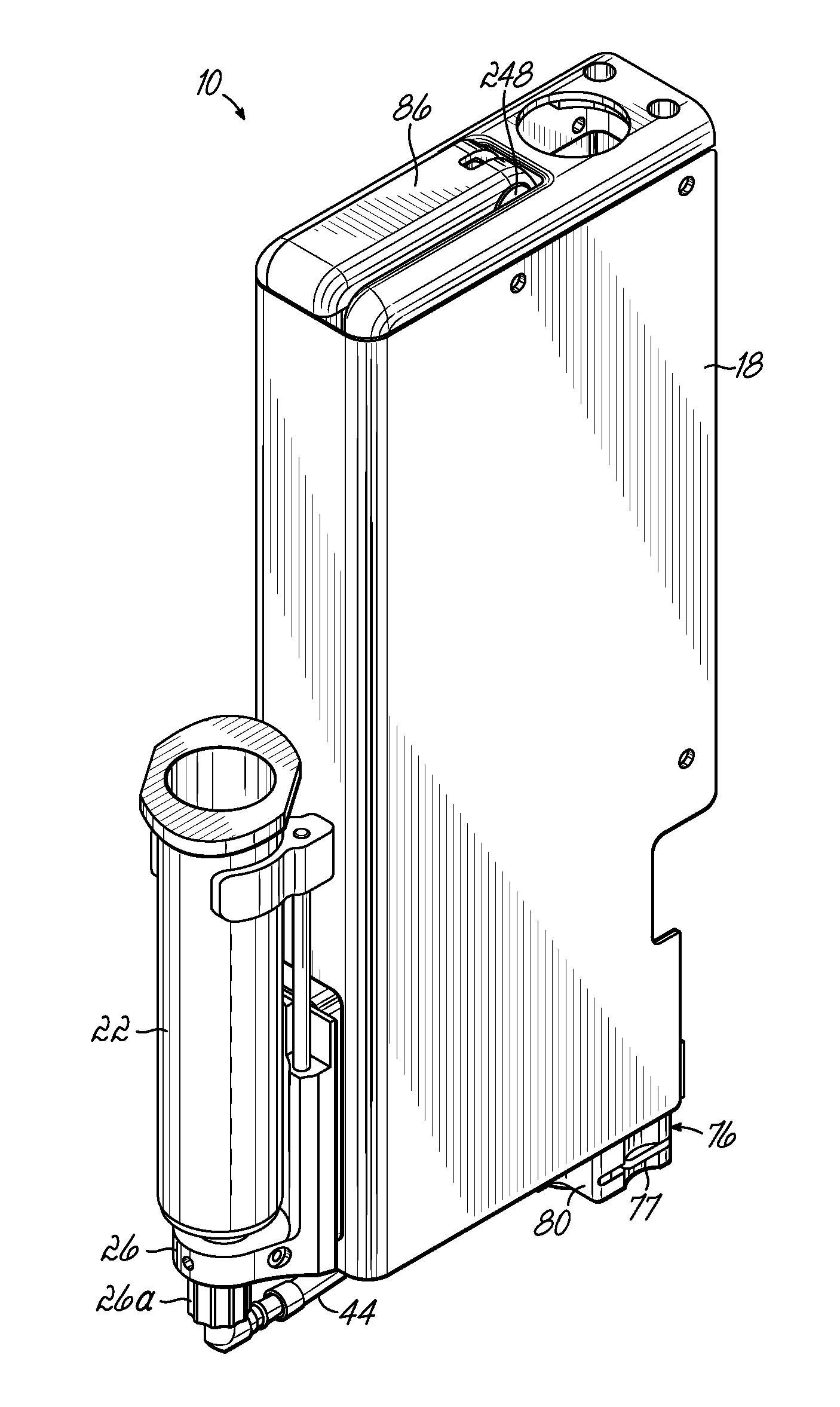
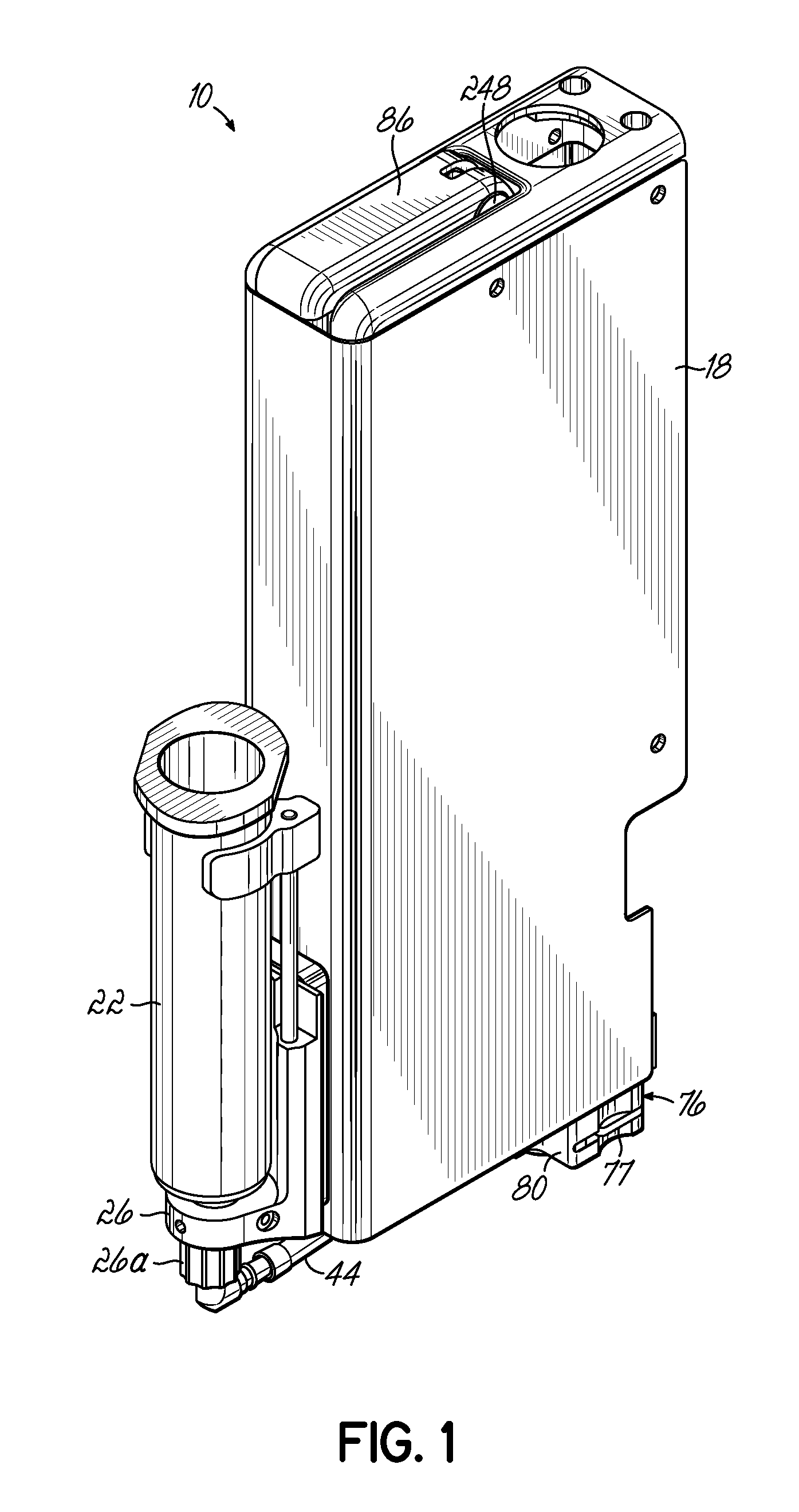
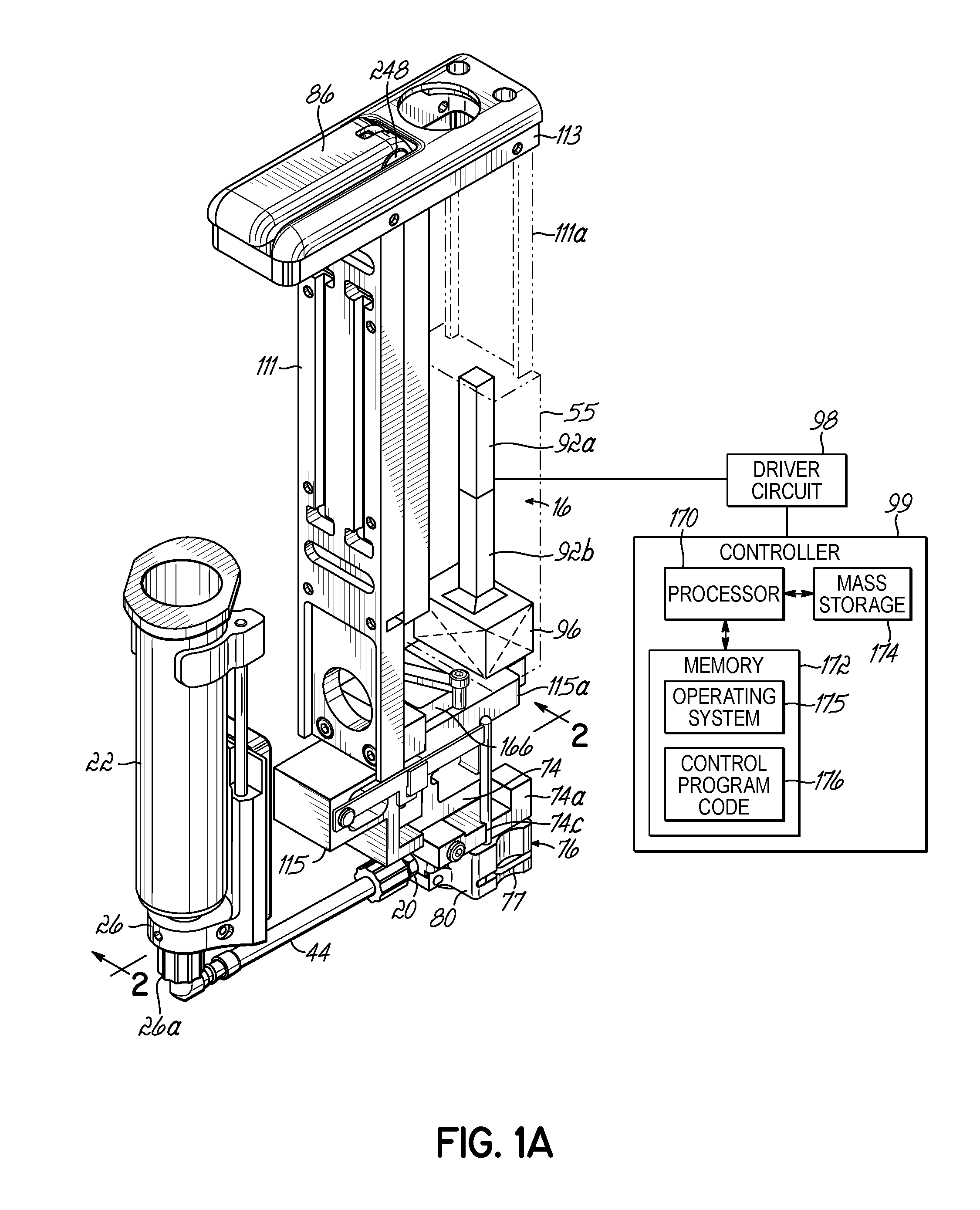
[0064]Generally, the embodiments of the invention are primarily directed to a dispensing valve in the form of a modular jetting device that is modular in a number of respects. One aspect is that the valve internal to the fluid module of the modular jetting device can be actuated by either a pneumatic drive module, an electromagnetic drive module, or a piezoelectric drive module. Another aspect is that fluid material can be supplied to the fluid chamber of the fluid module of the modular jetting device from fluid supply modules comprising either a pressurized syringe or positive displacement pump. Another aspect is that the modular jetting device includes a fluid module that seals all the wetted parts from the valve drive module. By the use of this design, the valve drive modules do not penetrate the fluid module, but rather ...


PUM


Abstract

Modular devices for jetting a fluid material and components for modular jetting devices. The devices may include a pressurized air or positive displacement pump fluid supply module to supply a fluid module inlet. A syringe may feed material through a check valve to a positive displacement pump, which feeds material through another check valve to the fluid module. Inside the fluid module is a valve element moved to contact a valve seat and jet a droplet of material by contact between an external drive pin and a movable element of the fluid module. Either a piezoelectric actuator, a pneumatic actuator, or another actuator may move the drive pin. A controller may coordinate the supply of fluid from the positive displacement pump with the rate at which material is jetted. The fluid module and positive displacement pump are easily removable from the jetting device.

Description

CROSS-REFERENCE TO RELATED APPLICATIONS[0001]This application is related to application Ser. No. ______, filed on even date herewith, and entitled “PNEUMATICALLY-DRIVEN DISPENSING VALVES WITH VARIABLE DISPENSING VELOCITY” (Attorney Docket No. NOR-1447US), which is hereby incorporated by reference herein in its entirety.BACKGROUND[0002]The invention relates generally to the application of fluid materials and, in particular, to devices for use in jetting fluid materials.[0003]Jetting devices may require different types of dispensing valves, or dispensing valve components, that are dedicated to different types of dispensing applications in electronic industry applications in which minute amounts of a fluid material is applied onto a substrate. A “jetting device” is a device which ejects, or “jets”, a droplet of material from the dispenser to land on a substrate, wherein the droplet disengages from the dispenser nozzle before making contact with the substrate. Thus, in a jetting type di...

Claims


Application Information

Patent Timeline
IPC IPC(8): A62C37/20
CPCB05C5/0291B05C5/0225B05D1/26H05K3/10B05B1/304B05B1/3046B05C5/02B05C5/0237B05C5/027B05C11/1002B05C11/1013B05C11/1034F16K31/1221
Inventor AGUILAR, STANLEY CRUZAHMADI, MANIDES JARDINS, STEPHEN RUSSELLFISKE, ERIKMEIER, MARKQUINONES, HORATIORATLEDGE, THOMASWRIGHT, ROBERT JAMES
Owner NORDSON CORP
Why Eureka
Try Eureka