Structure for strengthening of building column structures

a technology for building columns and structures, applied in the field of earthquake-resistant structures for strengthening building structures, can solve the problems of large tensile force, and inability to protect against earthquakes in other countries including korea, and achieves high durability, flexibility and strength, and is easy to be coupled or assembled. , the effect of large binding force and tensile for

Inactive Publication Date: 2013-03-07
IND ACADEMIC COOPERATION FOUND KEIMYUNG UNIV
View PDF29 Cites 21 Cited by
  • Summary
  • Abstract
  • Description
  • Claims
  • Application Information

AI Technical Summary

Benefits of technology

[0009]To overcome the above problems, it is an object of the invention to provide an optimal earthquake-resistant structure for strengthening building column structures, which is light and which is capable of providing high combinability or assembleability, high durability, flexibility and strength and no corrosion.
[0014]According to the present invention, the earthquake-resistant strengthening structure is light, can be easily coupled or assembled, and provides a large binding force and tensile force by structural engagement between pieces of the strengthening plates and fusion of bonding materials. In addition, since the strengthening plates are made of glass fiber or carbon fiber, it is possible to provide an optimal earthquake-resistant strengthening structure having high durability, flexibility and strength with no corrosion.
[0015]In addition, since the strengthening plates consisting of a plurality of pieces, construction thereof is very simple. Further, since the pieces of the strengthening plates can be freely changed in their size and shape, the earthquake-resistant strengthening structure can be applied to a variety of building column structures.

Problems solved by technology

In recent years, many countries including Japan, India, Turkey, Iran and so on have often suffering from earthquakes which cause disasters including casualties and destruction of infrastructures such as bridges.
In addition, it has turned out that other countries including Korea are not safe against earthquakes.
However, in such an elastic design method, since a seismic force, which is one of design variables, is set to be too small, response displacement obtained based on this set seismic force may be remarkably underestimated compared to actual displacement and moment produced by a combination of gravity and bearing power may be also underestimated.
In addition, since stiffness of structures is evaluated based on the entire effective sectional stiffness rather than stiffness measured after the structures are cracked, corresponding response displacement is underestimated.
With the above problems in the conventional bridges, it is almost impossible to tear down, redesign and reconstruct the bridges according to a strict earthquake-resistant design standard due to budgetary limitations although the bridges are in danger of collapse in the event of earthquakes.
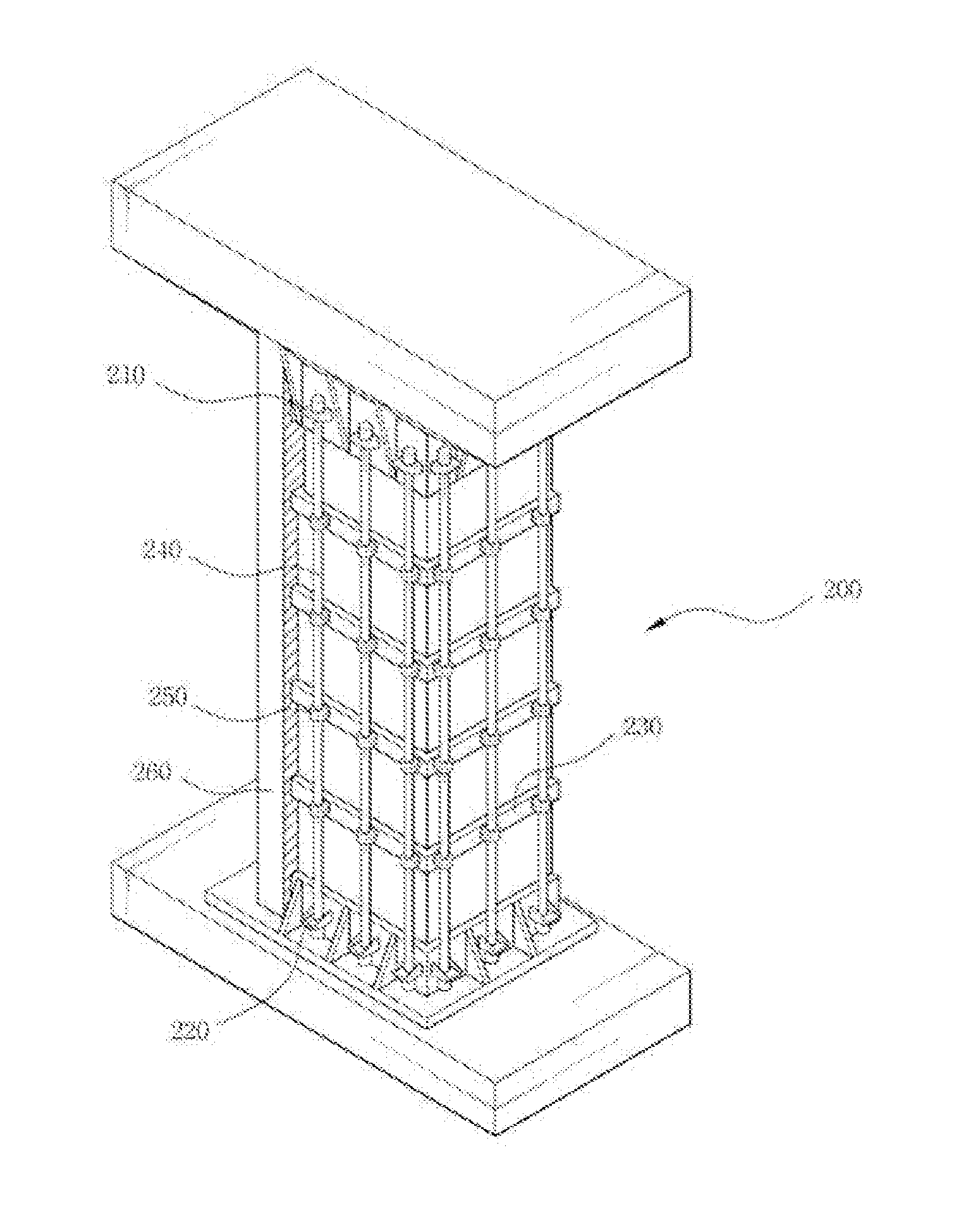
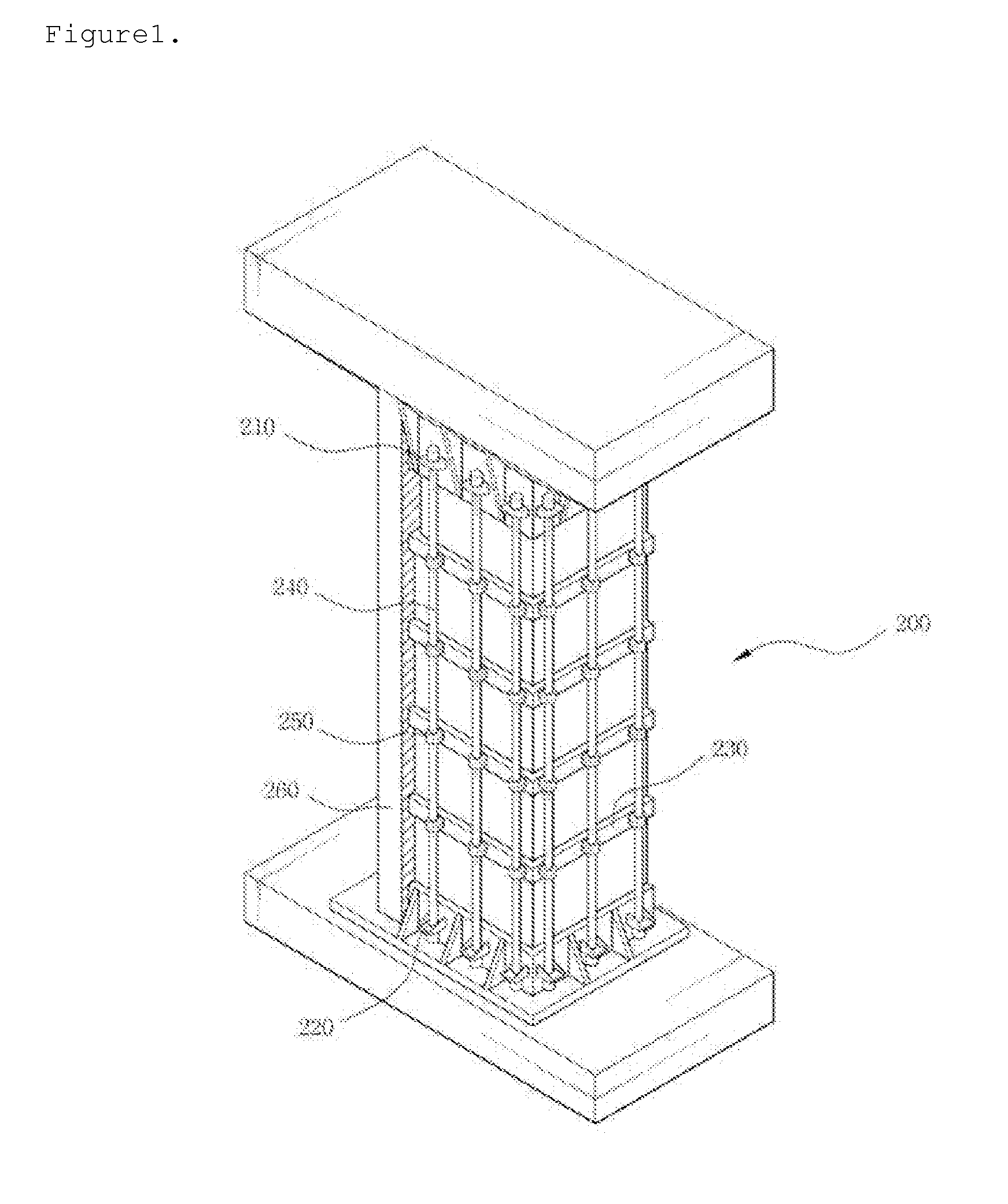
However, the above-structured earthquake-resistant strengthening equipment 200 of the conventional bridge lower structure provides a vertical binding force due to pre-stress without consideration of a horizontal binding force, particularly not considering earthquake-resistant strengthening of a fragile central area of the periphery of the bridge lower structure at all and has a problem of difficulty in stacking of the concrete strengthening layer 260 and construction due to manufacture of a separate work bench.
In addition, this above-structured earthquake-resistant strengthening equipment also has other problems of low durability due to external environments such as corrosion, and overweight of the entire earthquake-resistant structure.

Method used


Image

  • Structure for strengthening of building column structures
  • Structure for strengthening of building column structures
  • Structure for strengthening of building column structures

Examples


Embodiment Construction

[0022]The above and other objects, advantages, features and methods will be better understood when reading the following detailed description and the accompanying drawings. However, it should be understood that the present invention is not limited to the disclosed embodiments but may be embodied in other various forms. The disclosed embodiments are provided to describe the present invention in detail so that those skilled in the art can practice the technical ideas of the present invention.

[0023]In the drawings, elements of the embodiments are not shown in a limited sense but may be exaggerated for clarity. Throughout the drawings, same reference numerals denote same or similar elements.

[0024]In the specification, as used herein, the term “and / or” is meant to include at least one of elements arranged before and after. In addition, a singular form “a” or “an” is meant to include a plural form unless stated specifically otherwise. In addition, as used herein, the term “comprise(s)” or...


PUM

PropertyMeasurementUnit
specific gravityaaaaaaaaaa
durabilityaaaaaaaaaa
flexibilityaaaaaaaaaa

Abstract

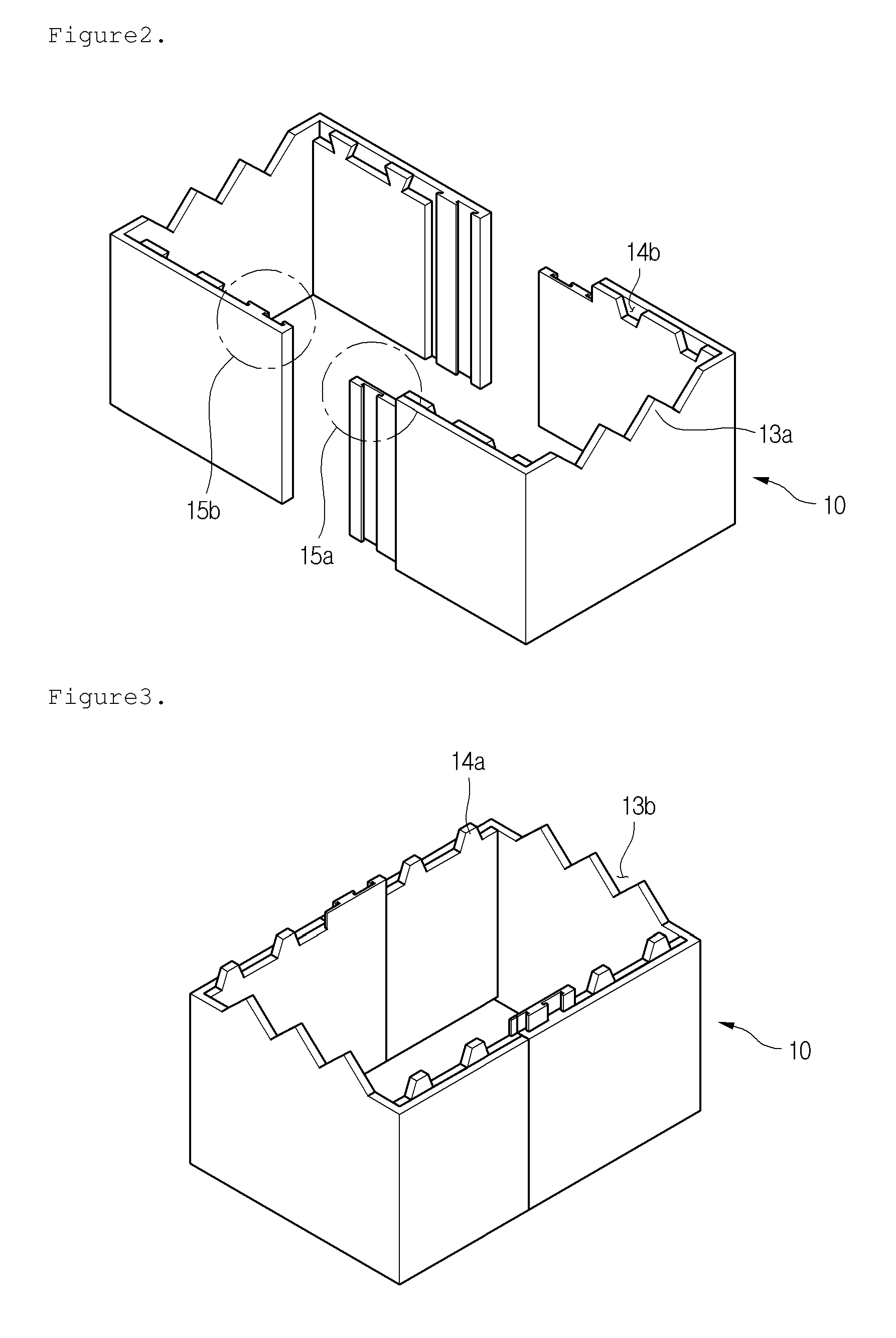
An earthquake-resistant strengthening structure for building column structures, includes: a plurality of strengthening plates which are made of fiber sheet, are coupled by a concavo-convex structure in a vertical direction and are coupled by a sliding coupler in a horizontal direction; and mortar which strengthens a coupling between the strengthening plates and adheres the strengthening plates to an earthquake-resistant object. The earthquake-resistant strengthening structure is light, can be easily coupled or assembled, and provides a large binding force and tensile force by structural engagement between pieces of the strengthening plates and fusion of bonding materials. In addition, since the strengthening plates are made of glass fiber or carbon fiber, it is possible to provide an optimal earthquake-resistant strengthening structure having high durability, flexibility and strength with no corrosion.

Description

BACKGROUND OF THE INVENTION[0001]1. Field of the Invention[0002]The present invention relates to an earthquake-resistant structure for strengthening building structures, and more particularly, to an optimal earthquake-resistant structure for strengthening building column structures, which is capable of providing high durability, flexibility and strength and no corrosion.[0003]2. Description of the Related Art[0004]In recent years, many countries including Japan, India, Turkey, Iran and so on have often suffering from earthquakes which cause disasters including casualties and destruction of infrastructures such as bridges. In addition, it has turned out that other countries including Korea are not safe against earthquakes. Therefore, there is a current keen need of a seismic design for structures such as bridges according to strict design standards.[0005]Conventional bridges have been designed according to an elastic design method based mainly on allowable stress, without a separate ...

Claims


Application Information

Patent Timeline
Patent Type & Authority Applications(United States)
IPC IPC(8): E04B1/98E04H9/02
CPCE04G23/0218E04G1/00E04G2023/0251E01D22/00E04B1/98E04G23/02
Inventor CHANG, CHUN HO
Owner IND ACADEMIC COOPERATION FOUND KEIMYUNG UNIV
Why Eureka
Try Eureka