

Touch panel, and touch-type input apparatus and control method therefor
a control method and touch technology, applied in the field of touch panel and touch-type input apparatus and control method therefor, can solve the problems of inability to detect multi-touch, cost rise, light transmittance impairment, etc., to reduce processing load, increase processing reliability, and determine more reliably
- Summary
- Abstract
- Description
- Claims
- Application Information
AI Technical Summary
Benefits of technology
Problems solved by technology
Method used
Image

Examples
first embodiment
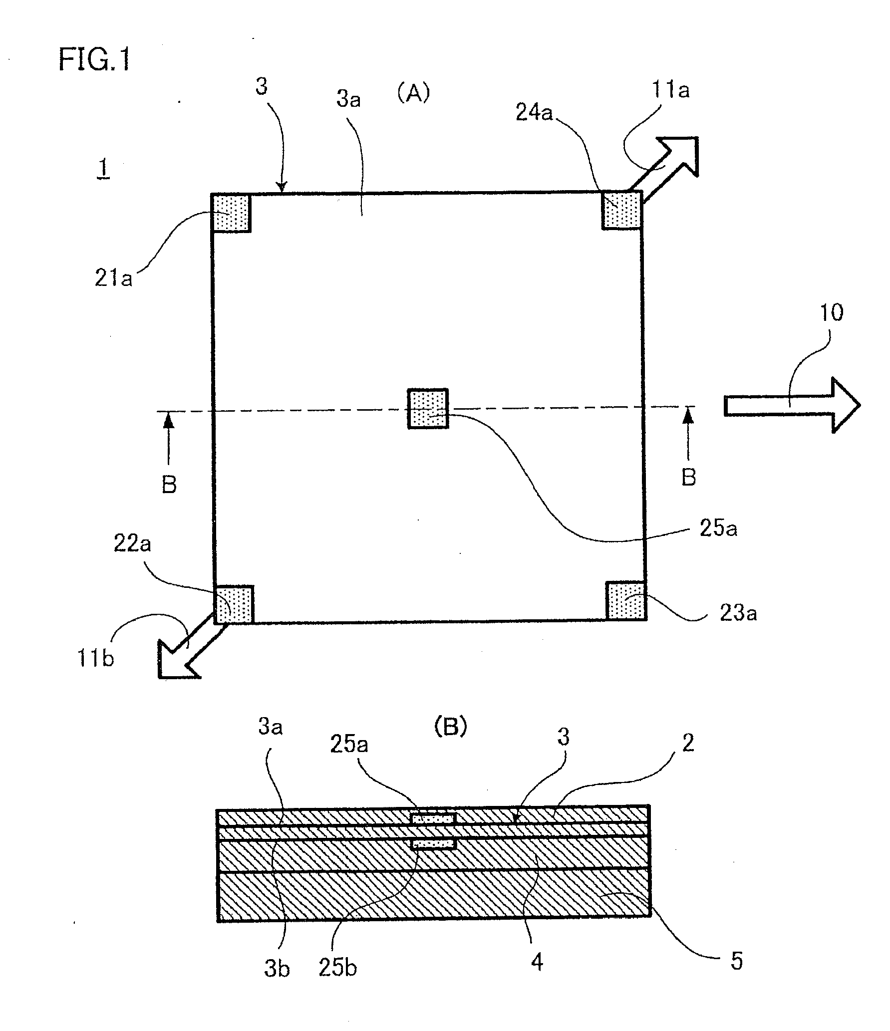
[0070]FIG. 1 shows a touch panel 1 according to the present invention, and in FIG. 1, (A) is a plan view and (B) is a section view along the line B-B in (A).
[0071]As shown in FIG. 1(B), touch panel 1 has such a sectional structure that a surface protection film 2, a piezoelectric sheet 3 having piezoelectricity, a rubber elastic body 4, and base body 5 are stacked in this order. More specifically, piezoelectric sheet 3 is bonded together with surface protection film 2, and rubber elastic body 4 is disposed between surface protection film 2 and base body 5. Rubber elastic body 4 permits deformation of piezoelectric sheet 3, and is formed from an elastomer or a gel material, however, the gap between piezoelectric sheet 3 and base body 5 may be left as a space.
[0072]Typically, touch panel 1 is arranged on the surface of a flat panel display (FPD) such as a liquid crystal display, organic EL display, plasma display, or electronic paper. Therefore, each element constituting touch panel 1...
second embodiment
[0087]FIG. 4 is a view corresponding to FIG. 1(A) showing a touch panel 1a according to the present invention. In FIG. 4, the element corresponding to the element shown in FIG. 1(A) is denoted by the same reference numeral, and overlapping description will be omitted. FIG. 4 shows a preferred electrode arrangement and preferred examples of tension directions 11a and 11b when stretching axial direction 10 is at diagonally 45 degrees.
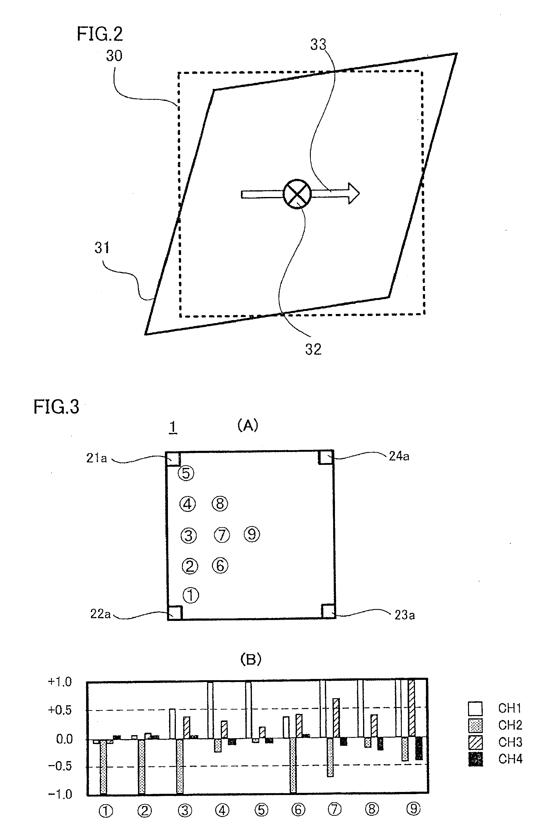
[0088]For example, when four corners of piezoelectric sheet 3 are stretched under the equivalent tension and fixed, the voltage patterns from electrodes 21a to 24a resemble even for different positions where a pressing operation is made, making it difficult to detect the position (see FIG. 11). On the contrary, under tension directions 11a and 11b as shown in FIG. 4, it is possible to obtain diverse voltage generation patterns as shown in FIG. 3(B) as is the case with the embodiment shown in FIG. 1, and to detect the position made more correctly by arrang...
third embodiment
[0092]FIG. 5 is a view corresponding to FIG. 1(A), showing a touch panel 1b according to the present invention. In FIG. 5, the element corresponding to the element shown in FIG. 1(A) is denoted by the same reference numeral, and overlapping description will be omitted.
[0093]FIG. 5 shows a modified example of the electrode configuration. More specifically, first electrodes 41a to 46a are provided on first main surface 3a of piezoelectric sheet 3, and electrodes 41a to 46a are designed to have different sizes, and the positions do not follow a regular rule. Although not illustrated, this also applies to second electrodes that are formed on the second main surface of piezoelectric sheet 3, so that they are opposed to first electrodes 41a to 46a.
[0094]While the tension direction is not illustrated, as the point to which tension is imparted, the part where electrode 42a and electrode 45a are situated, or the part where electrode 43a and electrode 46a are situated is conceivable. Of cour...
PUM
 Abstract
Description
Claims
Application Information