
Method and Apparatus for a Microfluidic Device

a microfluidic device and microfluidic technology, applied in the field of microfluidic devices, can solve the problems of affecting the use of the method and device, the inability to study the chemotaxis using conventional methods and devices, and the inability to achieve the effect of reducing the number of microfluidic devices, and achieving the effect of improving the efficiency of microfluidic devices

Inactive Publication Date: 2013-03-21
UNIV OF WASHINGTON CENT FOR COMMERICIALIZATION
View PDF4 Cites 36 Cited by
  • Summary
  • Abstract
  • Description
  • Claims
  • Application Information

AI Technical Summary

Benefits of technology

The present invention is a microfluidic device that allows for the safe transport of soluble factors through a membrane while protecting cell cultures, tissue cultures, and tissue explants from exposure to shear forces generated by fluid flow. The device is untethered from the substrate, which allows for spatial and temporal control of gradients onto conventionally prepared cell cultures and can also be used with different micro-devices. The device is transparent to allow for real-time observations of cell morphology and migration using conventional microscopy techniques. The invention also provides methods for controlling the delivery of soluble factors to cell cultures using the device. The device can maintain a stable source and sink of soluble factors for long-term and large-area concentration gradient generation.

Problems solved by technology

Conventional methods and devices employed to study chemotaxis have difficulties with cell seeding, gas and pH balance, and shear flow.
In addition, these methods and devices lack standardization and ease-of-use and present difficulties in transferring technology between labs of micro-fabrication expertise and biologists.

Method used


Image

  • Method and Apparatus for a Microfluidic Device
  • Method and Apparatus for a Microfluidic Device
  • Method and Apparatus for a Microfluidic Device

Examples


example

Gradient Generation

Device Setup

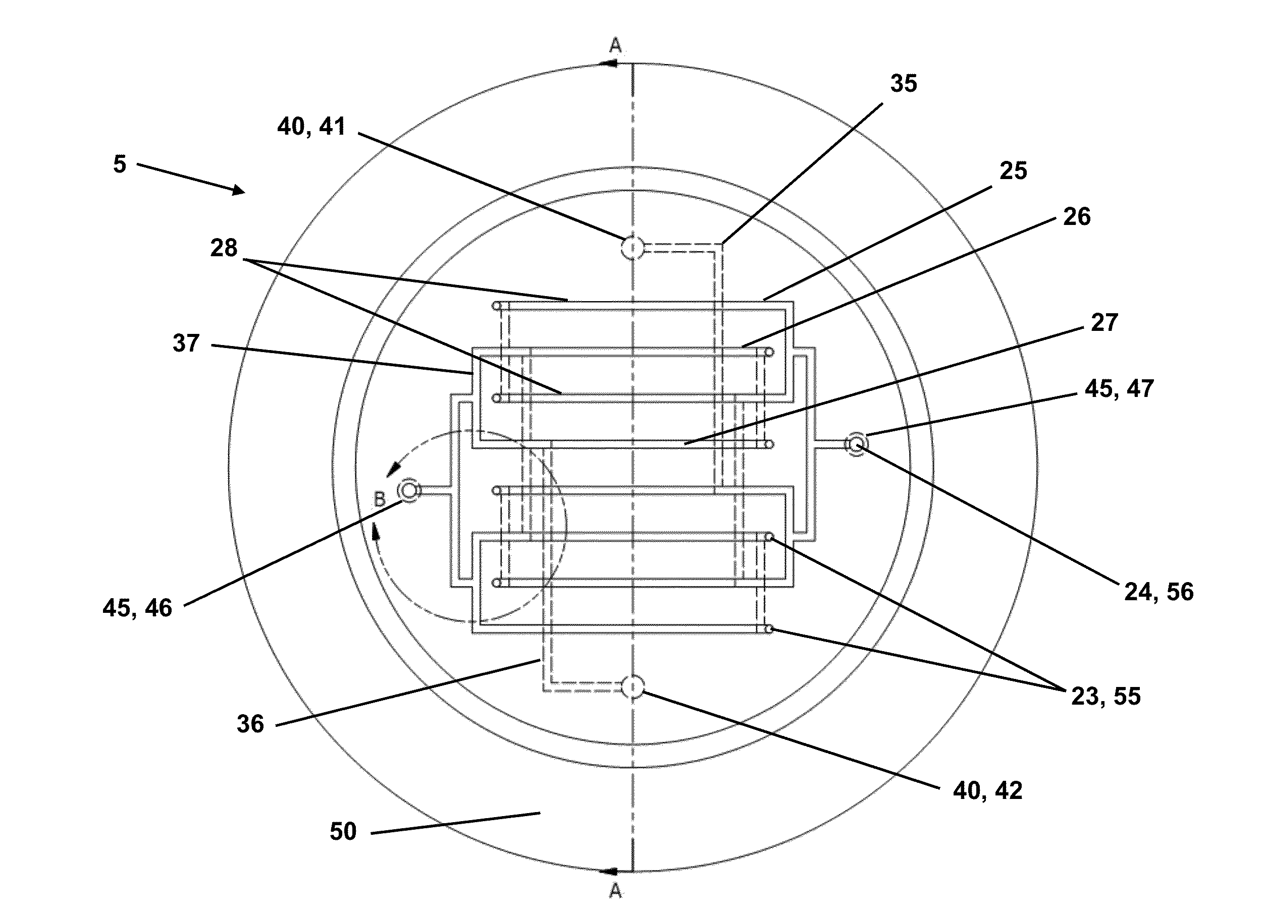
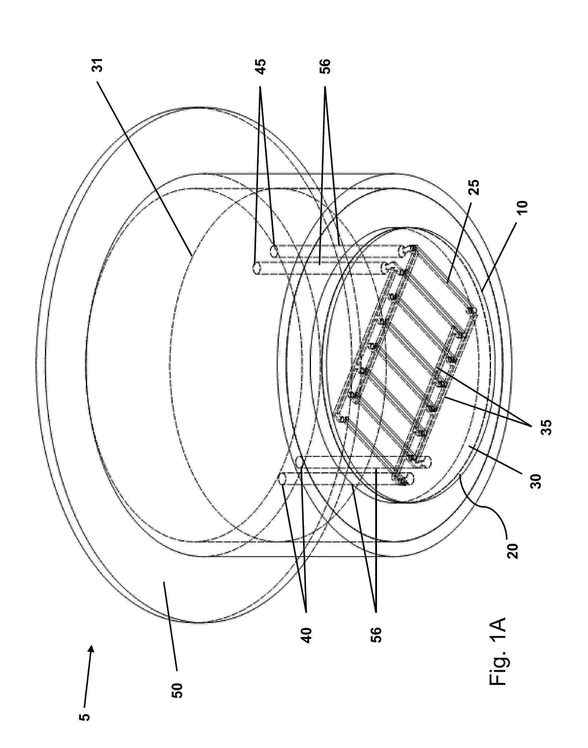
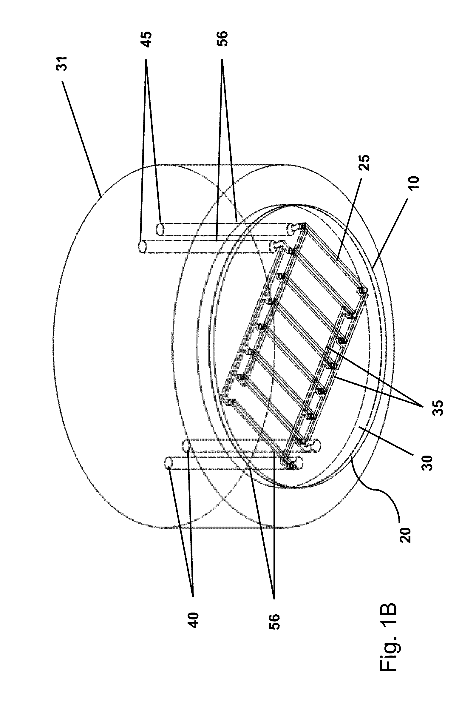
[0090]The microfluidic device 5 is pre-loaded with solutions through tubing and syringes connected to a dual-barreled syringe pump (Nexus, Chemyx Inc., Stafford, Tex.) before application. To generate a gradient 75, the microfluidic device 5 is loaded with a buffer and a solution containing the soluble factor of interest. To apply the microfluidic device 5 to a substrate, the device 5 is placed into a well 66 in a 6-well plate 65 pre-filled with a small volume of fluid (1-2 ml). The modular design serves two important purposes for device operation: (1) it frees the substrate from the microfluidic device 5 to simplify cell culture and (2) it allows us to introduce gradients of soluble molecules at any point in time to pre-established cell cultures. In this example, the microfluidic device 5 is operated at flow rates of 100 μl / hr to 200 μl / hr over the course of several hours. In a specific instance, flow rates of 100 μl / hr and 1000 μl / hr were applied diff...


PUM


Abstract

An microfluidic device and methods for its use, where the microfluidic device comprises: (a) a porous membrane, (b) a gradient layer defining a plurality of gradient micro-channels, where the gradient layer is coupled to a top surface of the membrane, (c) a distributor layer defining a plurality of distributor micro-channels, where the distributor micro-channels are coupled to the plurality of gradient micro-channels, where the distributor layer defines at least one inlet opening and at least one outlet opening, each inlet opening and outlet opening are coupled to the plurality of distributor micro-channels, and (d) self-supporting means coupled to one or more of the porous membrane, the gradient layer and the distributor layer.

Description

RELATED APPLICATIONS[0001]This application is a non-provisional of and claims priority to U.S. Provisional Application No. 61 / 535,236 for Method and Apparatus for a Transwell™ Microfluidic Gradient Generator for Cell Culture, filed Sep. 15, 2011, which is hereby incorporated by reference in its entirety.BACKGROUND OF THE INVENTION[0002]Chemotaxis is the phenomenon whereby somatic cells, bacteria, and other single-cell or multicellular organisms direct their movements according to certain chemicals in their environment. Chemotaxis plays essential roles in many biological processes including development, inflammation, wound healing, and cancer. Conventional methods and devices employed to study chemotaxis have difficulties with cell seeding, gas and pH balance, and shear flow. In addition, these methods and devices lack standardization and ease-of-use and present difficulties in transferring technology between labs of micro-fabrication expertise and biologists.SUMMARY OF THE INVENTION...

Claims


Application Information

Patent Timeline
Patent Type & Authority Applications(United States)
IPC IPC(8): F17D1/00
CPCF17D1/00B01L3/502761C12M23/16C12M25/04G01N33/5008B01L2200/0647B01L2200/0694B01L2300/0681B01L2300/0803B01L2300/0829B01L2300/0867B01L2300/0874B01L2300/0887B01L2400/0472Y10T137/85938Y10T137/0318B01F33/30B01F35/81
Inventor SIP, CHRISTOPHERFOLCH, ALBERT
Owner UNIV OF WASHINGTON CENT FOR COMMERICIALIZATION
Learn More