
Scattering film for organic el, and organic el light-emitting device equipped with same

a light-emitting device and organic el technology, applied in the field of scattering films, can solve the problems of low light utilization efficiency, low field-of-view dependence of organic el light-emitting devices, and mainly lost light, so as to improve light utilization efficiency, reduce field-of-view dependence, and improve the effect of light utilization efficiency

Active Publication Date: 2013-03-21
KIMOTO CO LTD
View PDF2 Cites 8 Cited by
  • Summary
  • Abstract
  • Description
  • Claims
  • Application Information

AI Technical Summary

Benefits of technology

The invention describes a way to improve the performance of organic EL light-emitting devices by adding a scattering layer with binder resin, microparticles and resin particles. This results in better light utilization and reduced field-of-view dependence, which means that the device can be viewed from different angles without distortion. The microparticles with a different refractive index from the binder resin help to achieve the reduced field-of-view dependence, while the larger resin particles are used to improve the light utilization efficiency without affecting the function of the microparticles. Overall, this approach results in improved performance of organic EL devices.

Problems solved by technology

First, because an organic thin-film layer, such as a light-emitting layer, constituting an organic EL light-emitting device has a higher refractive index than air, total reflection of emitted light tends to occur at an interface. Therefore, there is a problem that light utilization efficiency is lower than 20% of the emitted light, i.e., light is mostly lost.
The organic EL light-emitting devices also have a problem of field-of-view dependence.

Method used


Image

  • Scattering film for organic el, and organic el light-emitting device equipped with same
  • Scattering film for organic el, and organic el light-emitting device equipped with same

Examples


example 1

[0047]After the following constituent components were mixed under agitation into a coating liquid for scattering layer formation, the coating liquid was applied onto a support, i.e., a 100-μm-thick polyethylene terephthalate film (Lumirror T60 available from Toray Industries Inc.) by bar coating. Then the applied liquid was dried to give an 8-μm-thick scattering layer, i.e., a scattering film according to Example 1.

Formation Used In Example 1>Acrylic Polyol15.47 Parts(ACRYDIC A-804 Available from DIC Corporation, SolidContent: 50%, Refractive Index: 1.5)Isocyanate Curing Agent 3.78 Parts(TAKENATE D110N Available from Mitsui ChemicalsInc., Solid Content: 60%)Silicone Resin Particles 16.8 Parts(KMP-701 Available from Shin-Etsu Chemical Co., Ltd)(Average Particle Diameter: 3.5 μm, Refractive Index: 1.45)Zirconium Oxide 1.5 Parts(Average Particle Diameter: 0.5 μm, Refractive Index: 2.4)Diluting Solvent33.84 Parts

example 2

[0048]A scattering film according to Example 2 was obtained in the same manner as Example 1 except that the content of the zirconium oxide in the coating liquid for scattering layer formation used in Example 1 was changed to 3 parts by weight.

example 3

[0049]A scattering film according to Example 3 was obtained in the same manner as Example 1 except that the content of the zirconium oxide in the coating liquid for scattering layer formation used in Example 1 was changed to 6 parts by weight.


PUM


Abstract

Disclosed is a scattering film which can be used in an organic EL light-emitting device, in which the light utilization efficiency and field-of-view dependence, which have been problems so far in organic EL light-emitting devices, can be improved without interfering the two properties with each other. Specifically disclosed is a scattering film for an organic EL, which can be placed on the light emission surface side of an organic EL light-emitting device for use, and involves a scattering layer, wherein the scattering layer comprises a binder resin, microparticles having a different refractive index from that of the binder resin, and resin particles having a larger average particle diameter than that of the microparticles. The content of the microparticles is preferably 5 to 90 parts by weight relative to 100 parts by weight of the binder resin, and the content of the resin particles is preferably 100 to 300 parts by weight relative to 100 parts by weight of the binder resin.

Description

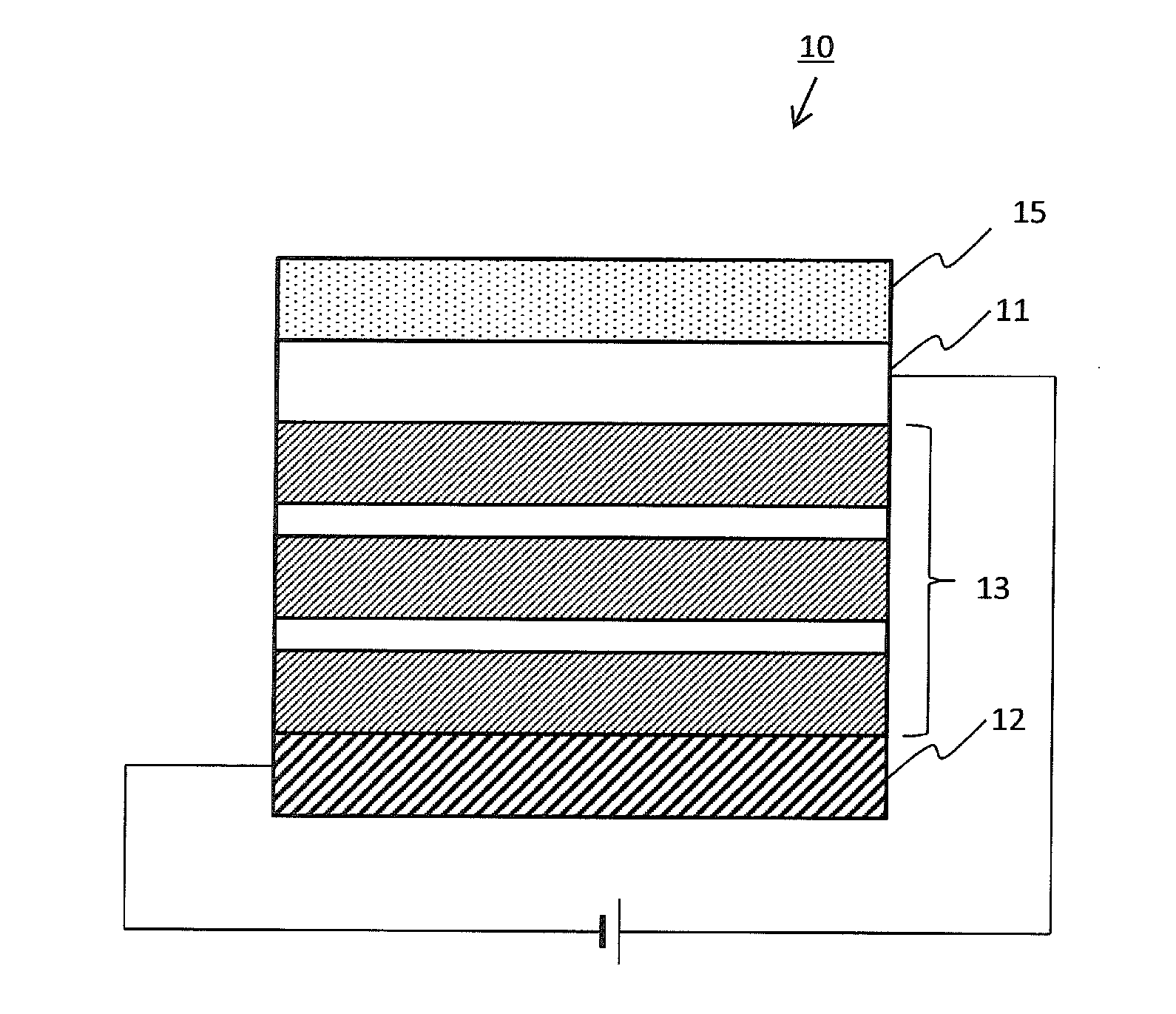
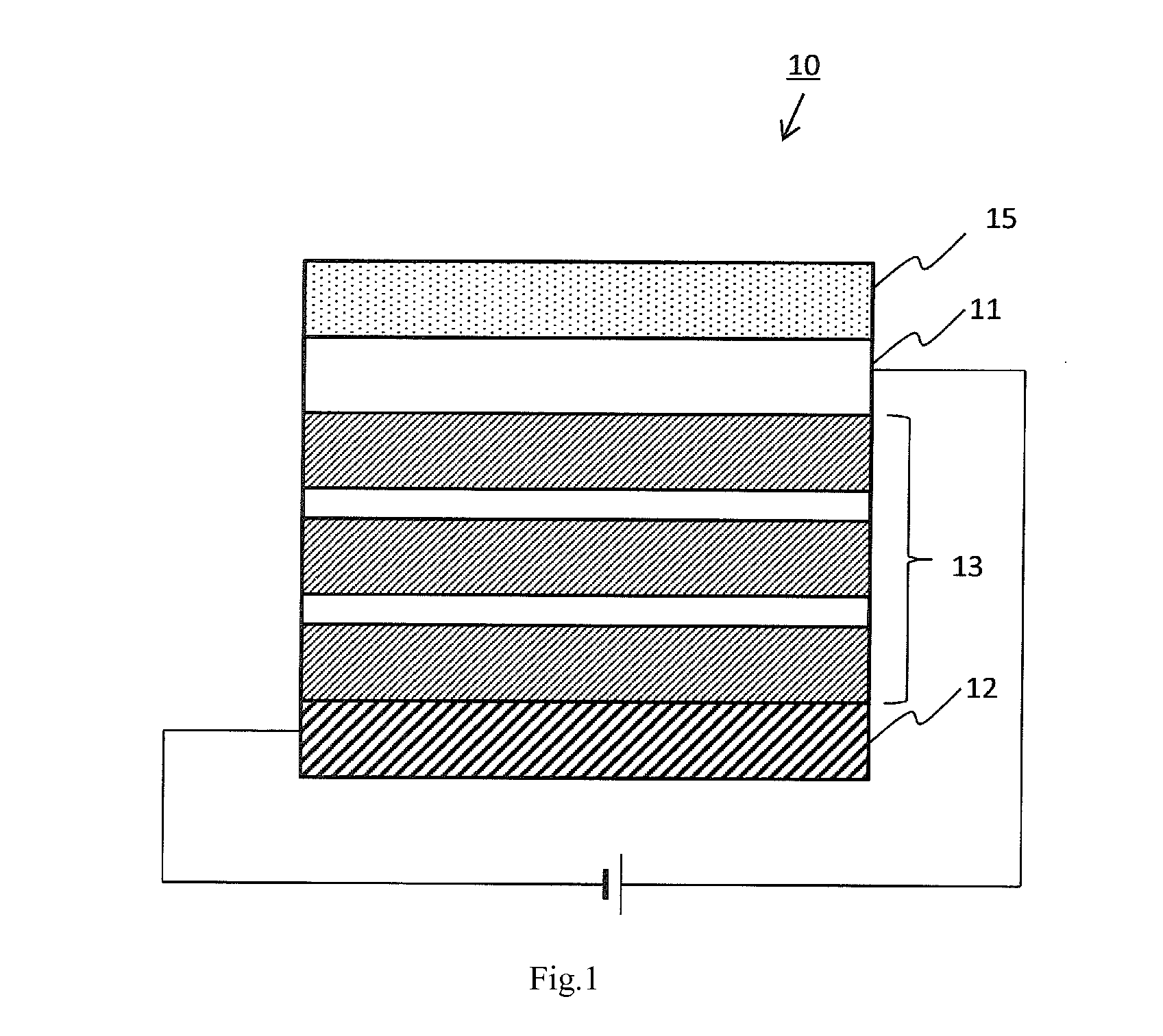
TECHNICAL FIELD[0001]The present invention relates to scattering films to be used in organic EL light-emitting devices.BACKGROUND ART[0002]There have been organic electroluminescent (organic EL) light-emitting devices that emit light by applying voltages to organic EL elements in which a light-emitting layer is interposed between a positive electrode (transparent electrode) and a negative electrode (back electrode). Since the organic EL light-emitting devices have advantages such as lightweight, small thickness, and low power consumption, they are used as backlights for liquid crystal displays and flat luminaires (Patent Document 1).[0003]Although the organic EL light-emitting devices have the excellent features described above, they have following problems.[0004]First, because an organic thin-film layer, such as a light-emitting layer, constituting an organic EL light-emitting device has a higher refractive index than air, total reflection of emitted light tends to occur at an inte...

Claims


Application Information

Patent Timeline
IPC IPC(8): G02B5/02H05B33/12
CPCG02B5/0242H01L51/504H01L2251/55H01L2251/5369H05B33/02H01L51/5268H10K50/13H10K50/854H10K2102/331Y10S428/917H10K2101/00
Inventor TAKAI, MASASHIISHIBASHI, TOSHIAKIKITAJIMA, KAZUYA
Owner KIMOTO CO LTD
Learn More