Permanent magnet generator

a permanent magnet generator and magnet technology, applied in the direction of electric generator control, dynamo-electric converter control, dynamo-electric machines, etc., can solve the problems of potential reactor core meltdown, long-term irreversible environmental damage, danger to and loss of human life, etc., to increase speed, less flux density, and less flux lines

Inactive Publication Date: 2013-03-21
LOVEJOY CONTROLS
View PDF12 Cites 31 Cited by
  • Summary
  • Abstract
  • Description
  • Claims
  • Application Information

AI Technical Summary

Benefits of technology

[0044]The present invention comprises a permanent magnet generator which is designed to couple to a power source, such as a turbine output shaft. The permanent magnet generator utilizes an internal mechanism consisting of a plurality of centrifugal fly weights positioning a coil spring-opposed spool piece which is in turn linked mechanically to magnets in respective alignment to provide magnet travel towards the center of rotation with increased speed due to the greater centripetal force of the flyweight assembly than the rare earth magnet assembly. A plurality of stator coils are positioned along the interior of an annular ring. The resulting magnet motions increase the air gap between the magnets and the stator coils lending fewer flux lines and less flux density to generate less voltage. This increasing air gap action with increased rotational speed is used to counter the inherent increase in coil voltage output in a self-regulating manner.

Problems solved by technology

Natural disasters, for example the May 2011 disaster following the tsunami at the Tokyo Electric Fukushima Nuclear Power Plant, evidence a flaw in the design of emergency reactor cooling water systems with potentially devastating consequences.
Lessons learned from past disasters include the irrefutable conclusion that the electrical power primary and backup systems feeding the reactor core cooling injection pump drive steam turbines are subject to failure by natural disaster leading to a potential reactor core melt down, danger to and loss of human life, and long term irreversible environmental damages.
A complication of Safety Related turbine speed control is the “open governor valve” start position to place the turbine in operation.
Failure to respond by closing the turbine governor valve to the speed throttling position quickly results in excess acceleration and turbine over-speed trip, or safety shut-down of the turbine.
Original equipment turbine speed control systems from the previous century were plagued with poor responding hydraulic control systems which often could not retard the acceleration quick enough due to susceptibility to operating oil contamination, air in the hydraulic oil and friction from long term inactivity.
Conventional permanent magnet generators can be coupled to turbine shafts to produce electrical power, but cannot provide electrical power over the required wide speed range, typically 500 RPM to 5,000 RPM due to basic electromagnetic properties.
This results in a ten-fold over-voltage output at 5,000 RPM which exceeds potentials and which will likely destroy electrical components in the rectification and shunt voltage regulation or limitation circuits.
For example, U.S. Pat. No. 5,789,822 to Calistrat et al. utilizes the low power generation of magnetic speed probes to self-power the electronic governor, but does not address the much greater electrical power demand of operating the governor steam valve and therefore must use a non-electric, hydraulic-positioned governor valve with accompanying high failure potential and complexity.
Due to the required radiation survival criteria for Safety Related turbine applications, complex electrical apparatus is not feasible, nor reliable, and the extreme range of speed of operation of a Safety Related turbine, again typically 500 RPM to 5,000 RPM, at a 1:10 ratio, is beyond the compensating ranges of the prior art.
Therefore a voltage compensation of increasing velocity can be accomplished by simultaneous increasing the air gap at the cost of decreasing generator efficiency.

Method used


Image

  • Permanent magnet generator
  • Permanent magnet generator
  • Permanent magnet generator

Examples


Embodiment Construction

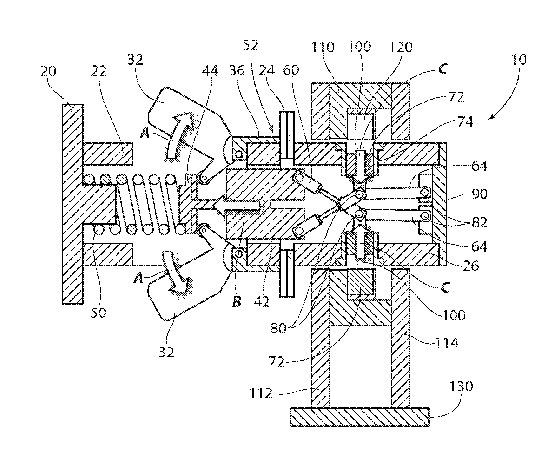
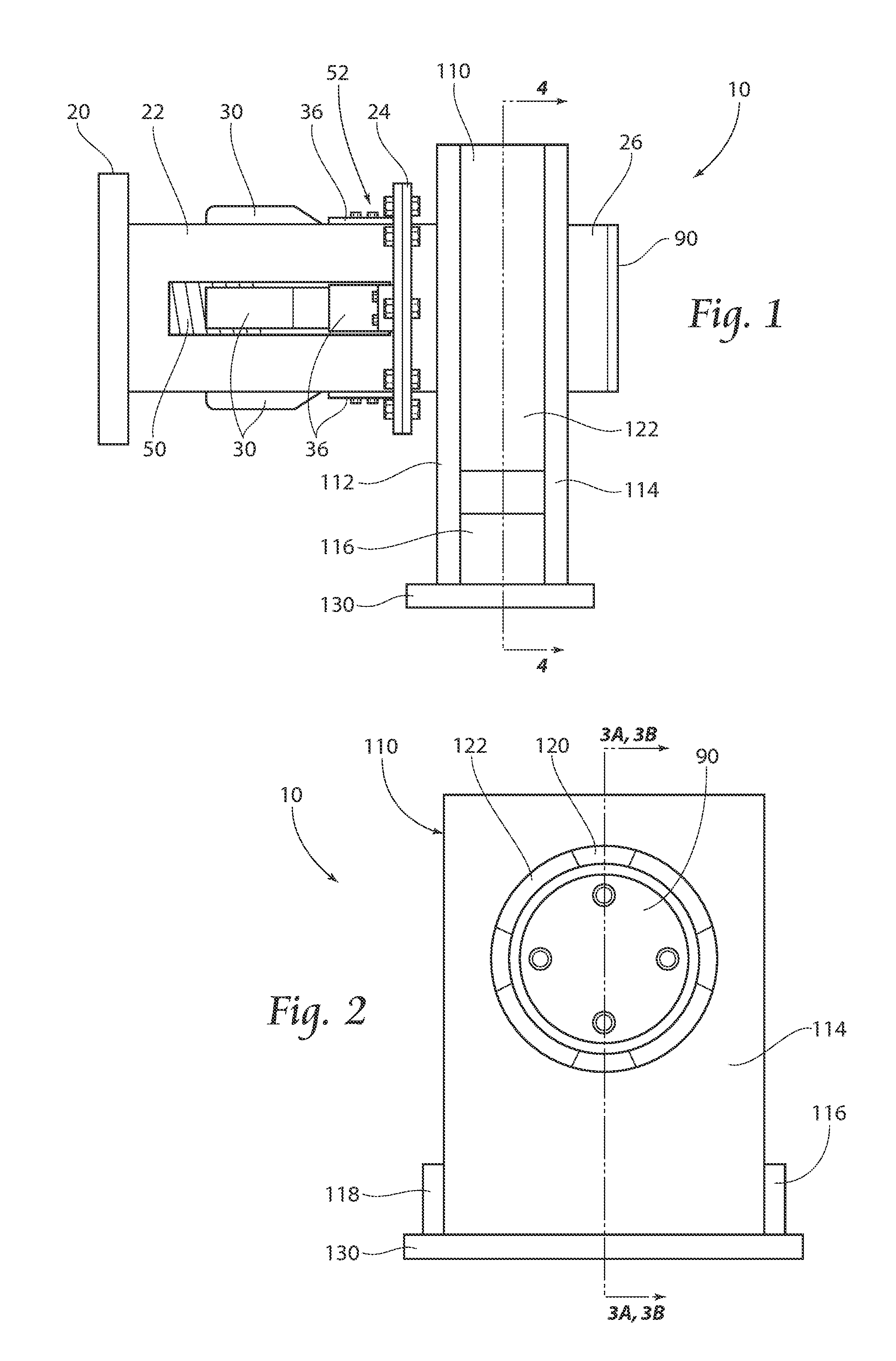
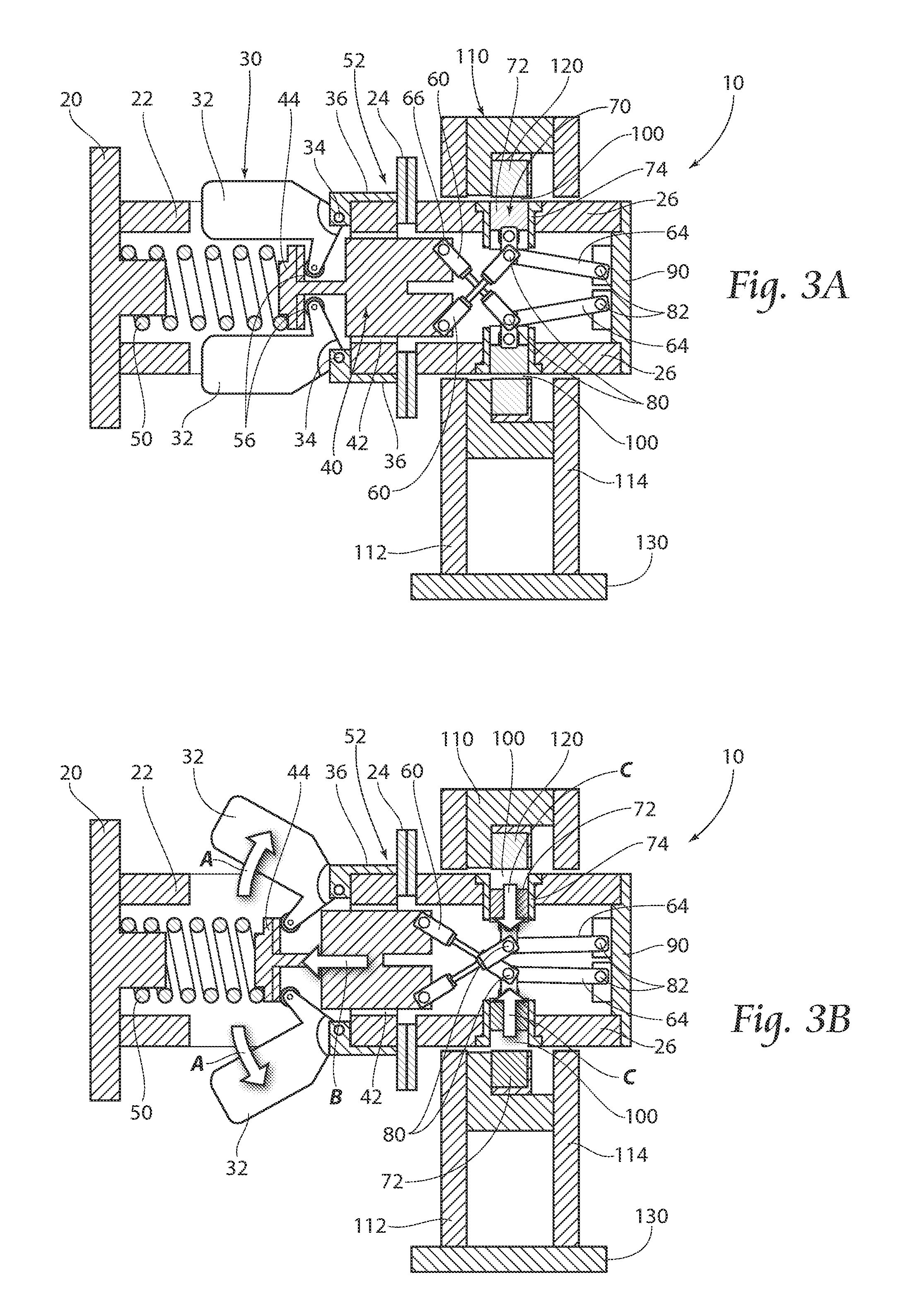
[0062]The permanent magnet generator 10 of the present invention couples to a source of rotational motion, such as a turbine. The permanent magnet generator consists primarily of two components including a rotor assembly 52 and a stator assembly 110. As shown in FIGS. 1, 2 and 5, the turbine mating flange 20 bolts to the turbine output shaft through flange bolt holes (not shown) or may thread on as per the turbine end shaft design, and also bolts to the inboard cylinder 22. Inboard cylinder 22 in turn bolts by flange 24 to the outboard cylinder 26 and forms the rotor assembly 52. The turbine bearings (not shown) support the permanent magnet generator rotor 52. The permanent magnet generator 10 stator assembly 110 supporting structure consists of a base 130, inboard stator bracket 112 and outboard stator bracket 114 forming a welded assembly with the stator wheel 122 affixed between the stator brackets 112 and 114. In operating position, the stator wheel 122 is centered about the rot...


PUM


Abstract

A permanent magnet generator having the unique feature of a speed proportionally adjusted air gap for self-regulation of coil output voltage over a wide range of operating rotational speed of a steam turbine to which the invention is coupled. The Permanent Magnet Generator rotor is supported by the turbine end shaft and the stator is supported by a bracket bolted to the turbine pedestal base or other rigid structure. The speed proportional air gap is accomplished through the use of a plurality of centrifugal flyweights in mechanical coupling to a spool piece under spring load and to corresponding rare earth magnets via linkage such that increasing rotor speed extends the flyweights outward from the rotor center of rotation and draws the rare earth magnets closer to the rotor center of rotation and thus increases the air gap.

Description

BACKGROUND OF THE INVENTION[0001]The present invention is a permanent magnet generator designed to be coupled with a power source such as a steam turbine. It is ideally suited for application in nuclear power plants. Natural disasters, for example the May 2011 disaster following the tsunami at the Tokyo Electric Fukushima Nuclear Power Plant, evidence a flaw in the design of emergency reactor cooling water systems with potentially devastating consequences. Lessons learned from past disasters include the irrefutable conclusion that the electrical power primary and backup systems feeding the reactor core cooling injection pump drive steam turbines are subject to failure by natural disaster leading to a potential reactor core melt down, danger to and loss of human life, and long term irreversible environmental damages.[0002]In order to lessen the probability of disaster and its associated consequences, the steam turbine controls for the Safety Related (as defined by the United States C...

Claims


Application Information

Patent Timeline
Patent Type & Authority Applications(United States)
IPC IPC(8): H02P9/48
CPCH02K21/025H02P9/48
Inventor LOVEJOY, KIM A.
Owner LOVEJOY CONTROLS
Why Eureka
Try Eureka