
Collimator for Medical Imaging and Fabrication Method

a collimator and medical imaging technology, applied in the field of photon collimators, can solve the problems of increasing the difficulty of collimator fabrication, increasing the cost of forming operations, and reducing the efficiency of laser sintering complex grid patterns of the size necessary for medical imaging photon collimators, etc., and achieves cost-effective effects. fewer forming operations

Active Publication Date: 2013-03-28
SIEMENS MEDICAL SOLUTIONS USA INC
View PDF14 Cites 16 Cited by
  • Summary
  • Abstract
  • Description
  • Claims
  • Application Information

AI Technical Summary

Benefits of technology

The present invention relates to the creation of a photon collimator that can be made from tungsten, molybdenum, or other photon-attenuating alloys. This collimator can be used in human-sized medical imaging equipment and meets the aperture variation tolerances required for such equipment. Additionally, the invention provides a method for fabricating a non-lead alloy photon collimator using cost-effective techniques and equipment. Furthermore, the invention reduces the number of forming operations required to create a matrix-like grid of individual aperture holes on a one-by-one basis.

Problems solved by technology

Tungsten (W) and Molybdenum (Mo) alloys are being considered as lead substitutes in collimators, but their hardness and relatively high melting temperatures make them more difficult to fabricate for collimators.
Some low energy-level collimators have been fabricated from molybdenum foil, but the foil thickness is too thin for the photon energy levels and density normally required for human medical imaging apparatus.
However, laser sintering complex grid patterns of the size necessary for medical imaging photon collimators is relatively time consuming and expensive.
Tungsten and molybdenum alloys are not as easily cast as lead to meet high precision tolerances required for medical imaging collimators—often requiring less than 1 / 20 degree variation between adjoining apertures.
Due to material hardness properties, tungsten alloys are not readily calendered in precision foil strips of sufficient thickness for medical imaging collimators, or readily mechanically machined (e.g., by drilling or milling).
It is difficult to maintain inter-aperture size, shape and spacing variation within acceptable tolerances by mechanical machining techniques.
Mechanically machining or thermal ablation cutting such a large quantity of individual apertures is time consuming and costly.

Method used


Image

  • Collimator for Medical Imaging and Fabrication Method
  • Collimator for Medical Imaging and Fabrication Method
  • Collimator for Medical Imaging and Fabrication Method

Examples


Embodiment Construction

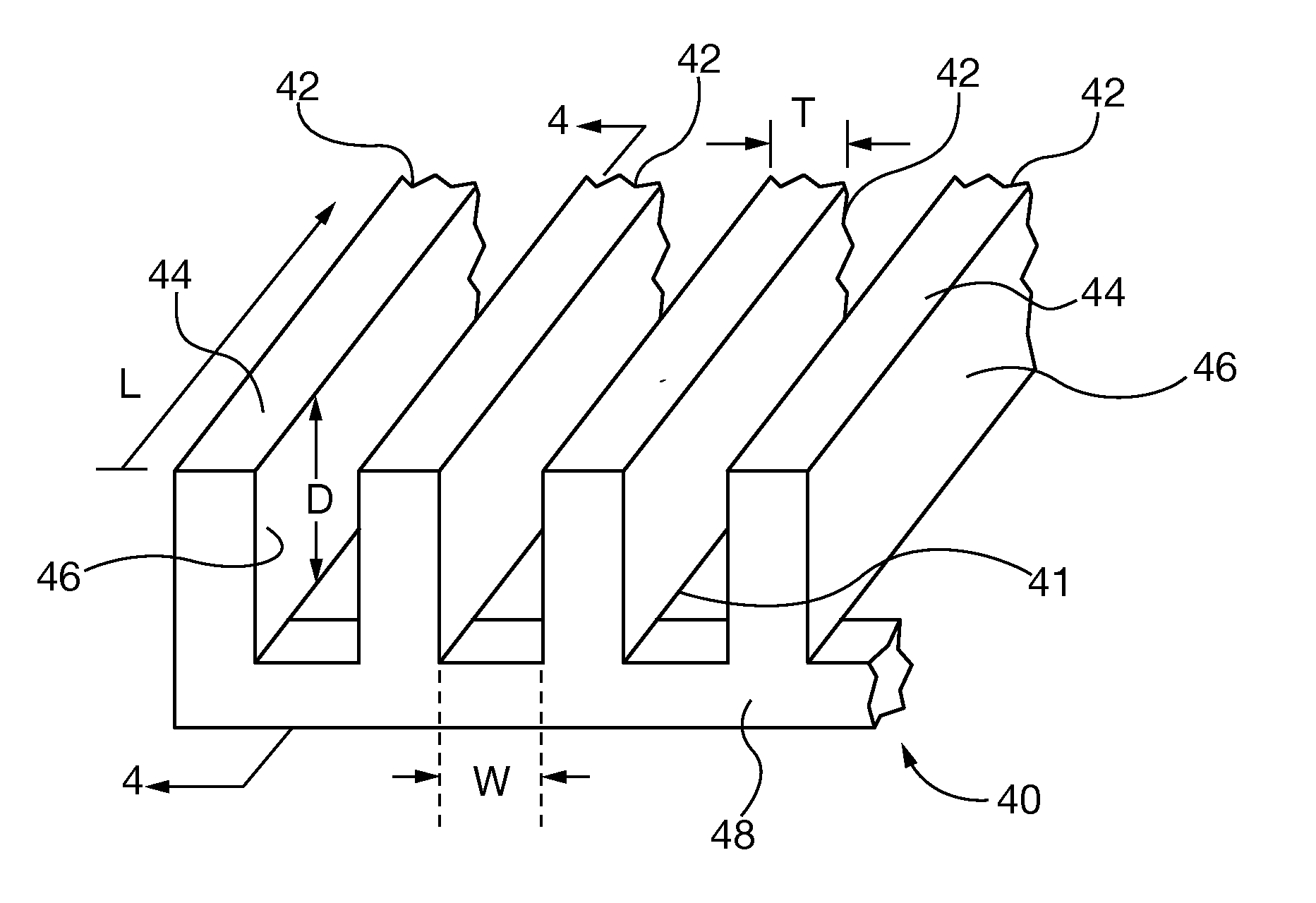
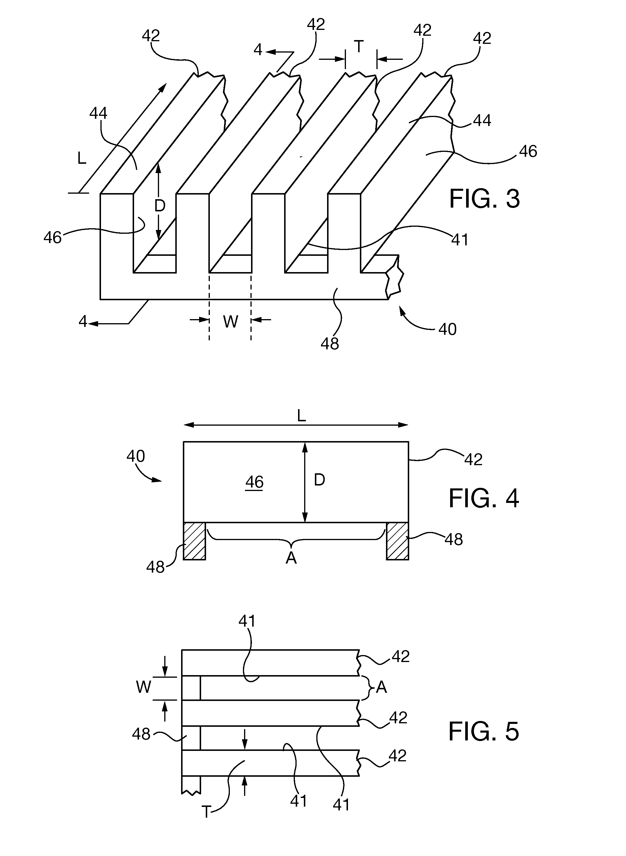
[0037]After considering the following description, those skilled in the art will clearly realize that the teachings of my invention can be readily utilized in the fabrication of photon collimators, comprising a block of photon-attenuating material, including lead or non-lead alloys, such as by way of non-limiting example tungsten or molybdenum alloys, defining a plurality of integrally formed septa slats, each slat having an elongated length dimension greater than its thickness and depth dimensions, and oriented in an opposed pattern array that is laterally spaced relative to its thickness dimension; and an aperture channel defined between each pair of opposed slats. The slats are fabricated by cutting the elongated aperture channels with EDM or laser thermal ablation machining. The slats and supporting structure may also be fabricated by laser sintering non-lead alloy powders, such as powders comprising tungsten or molybdenum alloy powders.

[0038]FIGS. 3-5 show an embodiment of a on...


PUM

PropertyMeasurementUnit
widthaaaaaaaaaa
lengthaaaaaaaaaa
lengthaaaaaaaaaa

Abstract

A photon collimator, suitable for use in medical imaging equipment, is constructed from a block of photon-attenuating material, such as solid tungsten or molybdenum alloy that defines a plurality of integrally formed septa slats. Each slat has an elongated length dimension greater than thickness and depth dimensions, and is oriented in an opposed pattern array that is laterally spaced relative to its respective thickness dimension. An aperture channel is defined between each pair of opposed slats. Rows of integrally formed slats in one block or separately affixed blocks may be stacked on each other at skewed angles to form two-dimensional grids of apertures having polygonal cross sections. The slats may be formed by electric discharge or laser thermal ablation machining, such as by a sequential passing of an EDM wire cutting head along the pattern array, repeating sequential cutting of respective channel depth and width.

Description

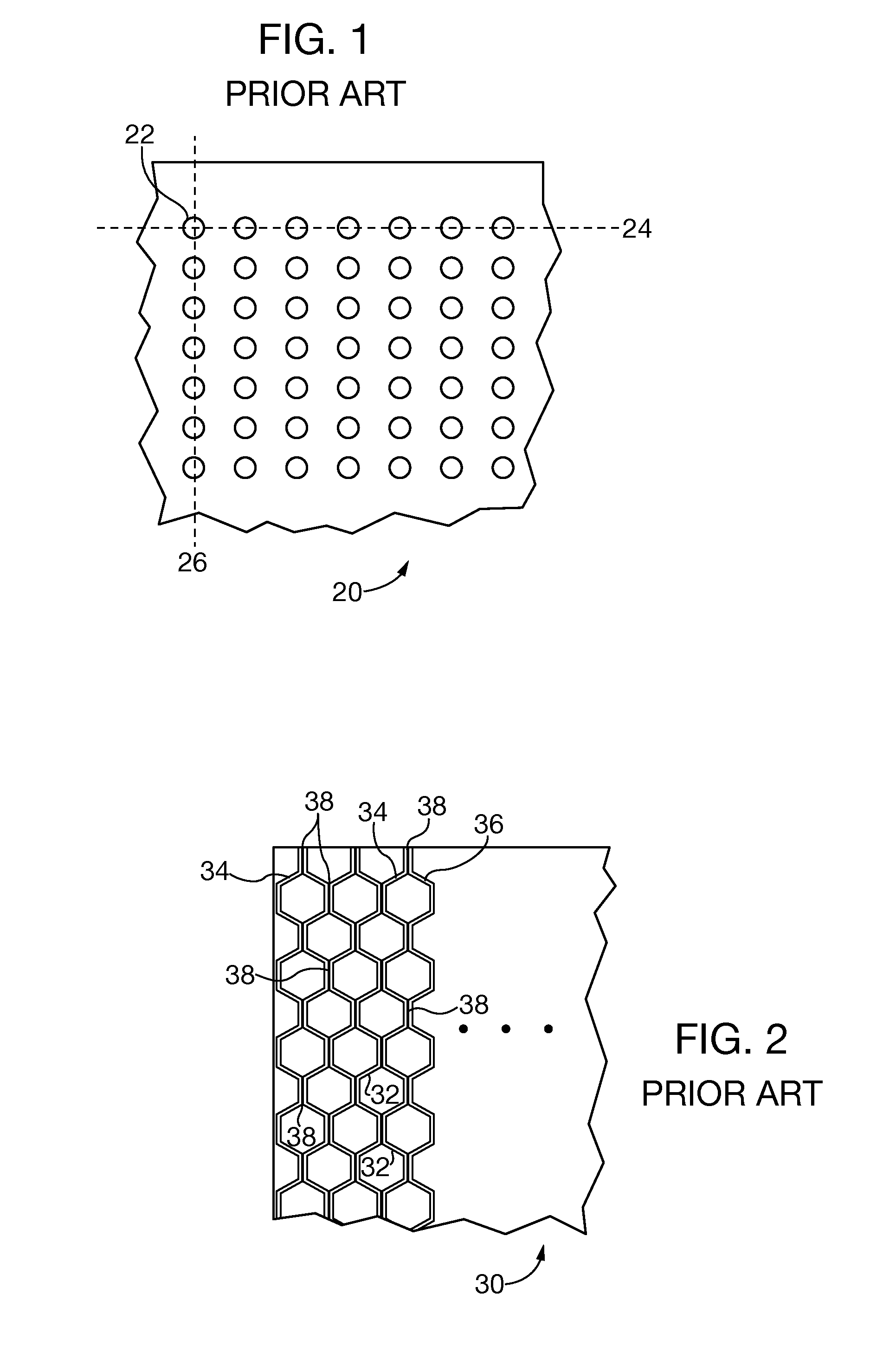
CLAIM TO PRIORITY[0001]This application claims the benefit of co-pending United States provisional patent application entitled “Crossed-Slat Collimator Formed by Wire-EDM Process”, filed Sep. 26, 2011 and assigned Ser. No. 61 / 539,015, which is incorporated by reference herein.BACKGROUND OF THE DISCLOSURE[0002]1. Field of the Invention[0003]The invention relates to photon collimators, and more particularly collimators suitable for medical imaging apparatus that are fabricated with electric discharge machining (EDM) techniques or other thermal ablation cutting techniques, such as laser cutting.[0004]2. Description of the Prior Art[0005]Photon collimators are utilized in medical imaging and therapy apparatus, such as gamma cameras, to allow passage of photons that have trajectory paths aligned with apertures that are defined by the collimator structure. Photons having non-aligned trajectory paths are blocked by the collimator structure. Known collimators are shown in FIGS. 1 and 2, and...

Claims


Application Information

Patent Timeline
Patent Type & Authority Applications(United States)
IPC IPC(8): G21K1/02B23K26/38B23P17/00B23H1/00
CPCB23H1/00G21K1/025B23K26/367B23K26/401Y10T29/49826B23H7/02B23H9/00G21K1/02B23K26/4015B23K26/364B23K26/40B23K2103/08B23K2103/50Y10T83/04Y10T83/0581
Inventor MALMIN, RONALD E.
Owner SIEMENS MEDICAL SOLUTIONS USA INC
Learn More