Charged body sensing system

a sensing system and charge body technology, applied in the direction of resistance/reactance/impedence, pulse technique, instruments, etc., can solve the problems of generating a greater linearity error in the outermost area, generating linearity errors such as offset lines, and the intersection matrix of row and column sensing electrodes of another conventional application also has the same drawback

Inactive Publication Date: 2013-03-28
HUANG LI HSIN
View PDF5 Cites 30 Cited by
  • Summary
  • Abstract
  • Description
  • Claims
  • Application Information

AI Technical Summary

Problems solved by technology

The problem with existing designs for the electromagnetic proximity sensing includes: 1. human body cannot be sensed when the human is to be closed; and 2.
The problem with existing designs for the capacitive proximity sensing and positioning includes:1. The RF signal is easily generated or the capacitive proximity sensing is easily affected by the RF signal.2. The sensing is interfered by the moisture.
The induction cannot be operated in humid environment.3. The poor SNR, the lower sensitivity, the small variation of the induced capacitance of the large object cannot be monitored, or the small capacitance variation cannot be monitored due to the large background capacitive environment is generated by the large object.4. The resistance of the ITO on the sensing electrode will be influenced when the capacitive proximity sensing is designed as the touch panel.5. The influence of the leakage current.6. Higher cost.
The drawback of the conventional independent matrix 502 is that, if the interpolation method is used to perform drawing and positioning functions in the conventional independent matrix 502, the greater linearity error will be generated in the outermost area, for example, draw a straight line will produce a linearity error such as offset lines 500.
In addition, the intersection matrix of row and column sensing electrode of another conventional application also has the same drawback as the above discussion.

Method used


Image

  • Charged body sensing system
  • Charged body sensing system
  • Charged body sensing system

Examples


first embodiment

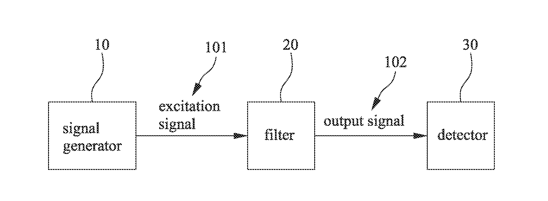
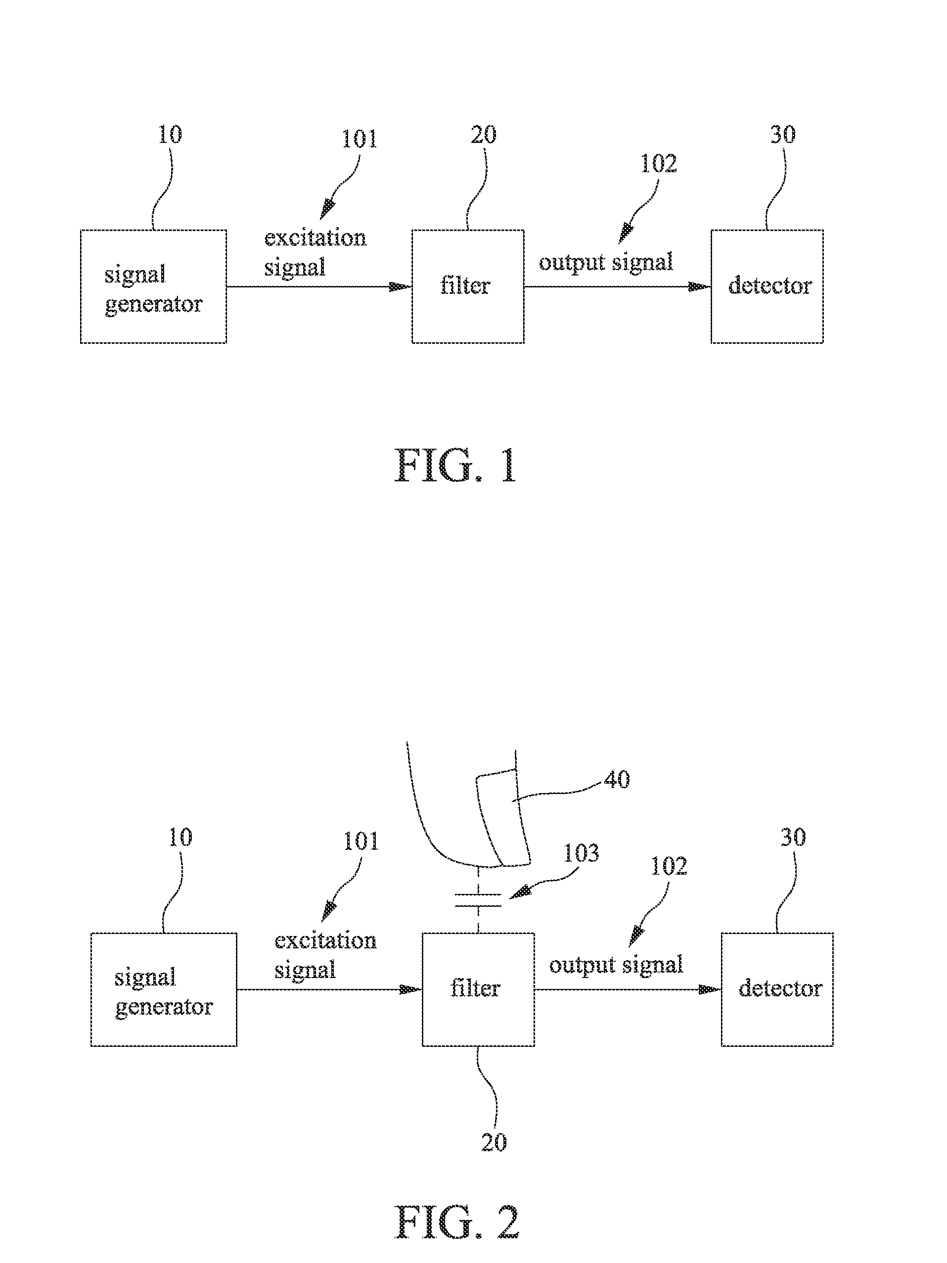
[0055]Please refer to FIG. 1 to FIG. 15. A charged body sensing system includes a signal generator 10, a filter 20, and a detector 30. The signal generator 10 generates at least one excitation signal 101. The signal generator 10 is coupled to the filter 20, and the filter 20 receives the excitation signal 101 from the signal generator 10. The filter 20 includes at least one resonant circuit 200, and the resonant circuit 200 includes at least one charged body sensing unit 21. The charged body sensing unit 21 includes at least a charged body sensing electrode 211 and at least an impedance element 210. The filter 20 is coupled to the detector 30. The detector 30 is corresponding to an output signal of the charged body sensing unit 21 of the filter 20. An induced capacitance 103 is generated when the charged body neared or touched to the charged body sensing electrode 211, an output signal 102 of the charged body sensing unit 21 corresponding to the induced capacitance will be changed. ...

second embodiment

[0073]Please refer to FIG. 16. FIG. 16 is a schematic diagram showing an equivalent circuit in a second embodiment. The filter 20 is composed by an inductor Lp, a capacitor Cp and an input capacitance of current peak detector. The filter 20 is a LC band-pass filter. The signal generator 10 is a square wave generator, and the frequency is a center frequency of the band-pass filter. The signal transfer path is an electromagnetic coupling path. The filter 20 receives a coupled current signal. Now, the filter 20 is a LC parallel resonant circuit. When the excitation signal frequency equals to the resonant frequency of the filter 20, the signal-to-noise ratio and the sensitivity are the highest.

[0074]The coupling capacitance would be generated when the charged body 40 nears or touches the signal transfer path or the filter 20. The coupling capacitance will change the equivalent capacitance of the parallel resonant circuit, so as to the resonant frequency is to be changed. The capacitance...

third embodiment

[0080]Please refer to FIG. 17 to FIG. 19. FIG. 17 to FIG. 19 shows a further embodiment of the present invention. The filter 20 further includes a capacitor 201, an inductor 202, a multiplexer 203 and an amplifier / buffer 204. The amplifier / buffer 204 is provided for impedance transformation from the filter 20 to the detector 30 and amplifying the signal. The capacitor 201 is electrically connected with the inductor 202. The multiplexer 203 is electrically between the capacitor 201 and the inductor 202. The multiplexer 203 is electrically connected with the plurality of charged body sensing electrode 211. The signal generator 10 is coupled to the inductor 202. The filter 20 receives the excitation signal 101 from the signal generator 10. The amplifier / buffer 204 outputs an output signal 102 to the detector 30.

[0081]The detector 30 includes an analog-to-digital converter. The detector 30 is further electrically connected with a microprocessor 208. The microprocessor 208 is electricall...


PUM


Abstract

A charged body sensing electrode is provided which includes a signal generator, a filter and a detector. The signal generator generates an excitation signal, and the filter is coupled to the signal generator and receives the excitation signal from the signal generator. The filter includes at least one charged body sensing unit. The detector is coupled to the filter and detects an output signal corresponding to the filter. Accordingly, when the charged body neared or touched the charged body sensing electrode, the output signal of the filter will be changed. The trajectory, the velocity or the location of the charged body, or the impedance variation of the charged body sensing unit can be obtained by the change of the output signal of the filter which is detected by the detector.

Description

FIELD OF THE INVENTION[0001]The present invention relates to a charged body sensing system, and in particular to the change of the output signal of the filter can be detected by the detector to obtain the trajectory, the velocity or the location of the charged body, or an impedance variation of the charged body sensing unit.BACKGROUND OF THE INVENTION[0002]There are many methods for an object proximity sensing and positioning. The methods include the capacitive sensing, an electromagnetic sensing, an optical sensing or an acoustic-type sensing, and so on.[0003]The electromagnetic sensing is that when the induction is occurred, the magnetic flux will be changed, and the distance variation of the proximity object can be inferred.[0004]The common method is electromagnetic sensing method, which has two sensing plates, one is a signal emitting terminal, and another is a signal receiving terminal. When the object closed to induce the variation of magnetic flux, the location of the object ...

Claims


Application Information

Patent Timeline
Patent Type & Authority Applications(United States)
IPC IPC(8): G01R27/28
CPCH03K17/9622G06F3/044H03K2217/96073G06F3/04182
Inventor HUANG, LI-HSIN
Owner HUANG LI HSIN
Why Eureka
Try Eureka