Wide field of view monocentric lens system for infrared aerial reconnaissance camera systems

a monocentric lens and infrared aerial reconnaissance technology, applied in the field of optical systems, can solve the problems of inability to accept uav platforms, inability to realize infrared camera systems, and the '593 patent is too large for many uav applications, so as to minimize chromatic and spherical aberration, the effect of reducing the chromatic aberration

Active Publication Date: 2013-03-28
THE BF GOODRICH CO
View PDF1 Cites 79 Cited by
  • Summary
  • Abstract
  • Description
  • Claims
  • Application Information

AI Technical Summary

Benefits of technology

[0018]In a second aspect, a compact, light-weight, wide field of view optical system for a mid-wavelength infrared (MWIR) aerial reconnaissance camera is disclosed. For purposes of this disclosure, the MWIR band is considered as encompassing the band of radiation having a wavelength of about 3 to about 5 micrometers (3 μm-5 μm). The system includes a curved focal surface and a wide field of view monocentric lens system. The monocentric lens system includes a front shell lens element, a core lens element, and a first rear shell lens element and a second rear shell lens element. The front shell lens element and the first and second rear shell lens elements are concentrically arranged about the core lens element such that infrared radiation entering the monocentric lens passes sequentially through the front shell lens element, the core lens element, and the first and second rear shell lens elements and is focused onto the curved focal surface. The front shell lens elements and the rear first lens elements are made of material having a relatively higher refractive index or a relatively higher optical dispersion, or both, in the MWIR band, the material carefully selected to minimize chromatic and spherical aberration as well as secondary chromatic aberration and spherochromatism, and pass radiation in the MWIR band. The core lens element is made from a material having a relatively lower refractive index or a relatively lower optical dispersion, or both, in the MWIR band, and carefully selected to compensate for spherical and chromatic aberration as well as secondary chromatic aberration and spherochromatism.
[0019]As was the case with the LWIR embodiment, several preferred implementations of the MWIR embodiment are disclosed herein including specific materials for the front shell lens element, the core lens element and the rear shell lens elements. Preferred embodiments have a field of view of at least about 70 degrees, a focal length greater than 2.0 inches, and an F / # near unity (e.g. between about 0.9 and about 1.1). Preferred embodiments also feature near diffraction limited performance, the achievement of which is enabled by the selection of materials selected for the lens elements in the monocentric lens as described herein.

Problems solved by technology

While this trade off may be acceptable for larger manned aerial platforms, it is not acceptable for UAV platforms.
This objective is even more difficult to realize for infrared camera systems which generally use large diameter lenses and cryogenic coolers for the image detectors.
The camera system of the '593 patent is too large for many UAV applications.
Another means to increase the camera FOV is to increase the format size of the electro-optical detector array, also described in U.S. Pat. No. 5,668,593; however, larger detector arrays require a larger diameter lens system, which adds weight and increases camera size.
Still another means to provide a wide FOV is to utilize multiple cameras and combine the fields of view; however, such a configuration is mechanically cumbersome and requires significant post processing of the camera outputs.
It is significantly noted that although Chen describes a WFOV concentric ball lens assembly in combination with a curved focal surface detector array, he fails to provide any detail whatsoever for the lens design, fabrication, and performance.

Method used


Image

  • Wide field of view monocentric lens system for infrared aerial reconnaissance camera systems
  • Wide field of view monocentric lens system for infrared aerial reconnaissance camera systems
  • Wide field of view monocentric lens system for infrared aerial reconnaissance camera systems

Examples


first embodiment

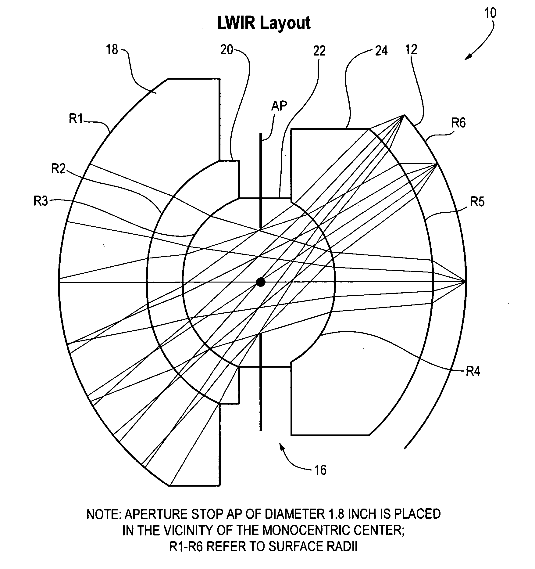
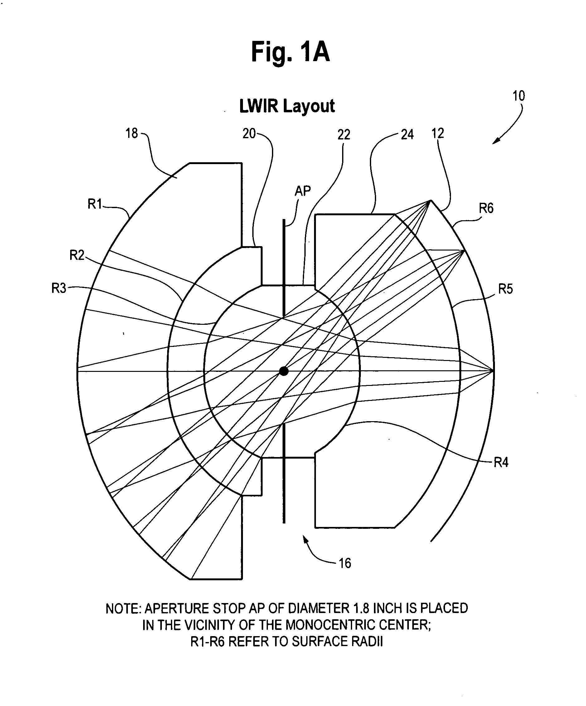
[0069]FIG. 1A is a layout of a compact, light-weight, wide field of view optical system 10 suitable for use in a long wavelength infrared (LWIR) aerial reconnaissance camera. The optical system 10 includes a curved focal surface 12. A curved focal plane detector (not shown in FIG. 1A; see FIG. 6) as described below is positioned at the curved focal surface 12. The pixels of the detector (or mosaic of detectors) convert scene energy into electronic image signals which are transferred via an output register, then digitized and sent to a memory or signal processing electronics in known manner.

[0070]The optical system 10 includes a wide field of view monocentric lens system 16. The monocentric lens system 16 includes a first front shell lens element 18 and a second front shell lens element 20. The monocentric lens system includes a core lens element 22 and a rear shell lens element 24. As shown in FIG. 1A, the first and second front shell lens elements 18 and 20 and the rear shell lens ...

second embodiment

[0079]FIG. 2A is an illustration of a layout of the LWIR optical system 10 similar to the embodiment in FIG. 1A. The general remarks regarding the construction and arrangement of the system of FIG. 1A apply to FIG. 2A, with the exception that the selection of specific materials is different. In FIG. 2A, front shell 18 is made from ZnS, front shell 20 is made from Ge, rear shell 24 is made from Ge and the core 20 is fabricated from GASIR-1. A controlled air gap 30 separates the rear shell element 24 from the curved detector focal surface 12.

[0080]The materials selected for the lens of FIG. 1A provide improved transmissivity at the longer wavelengths of the LWIR band as compared to the lens of FIG. 2A.

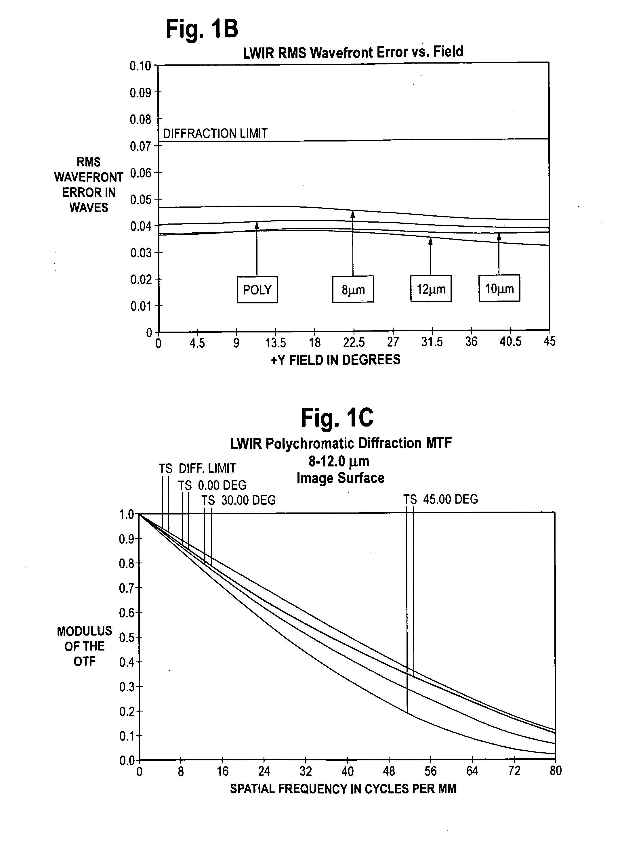
[0081]FIGS. 1B and 2B illustrate the RMS (root mean square) wavefront error for the lenses of FIGS. 1A and 2A, respectively.

[0082]FIGS. 1C and 2C show the polychromatic diffraction MTF for the lenses of FIGS. 1A and 2A, respectively.

[0083]FIGS. 1D and 2D depict the transverse ray fan plo...


PUM


Abstract

A wide field of view monocentric lens system for an infrared aerial reconnaissance camera includes front and rear lens shell elements and a core lens element, with the number of front and rear shell lens elements depending on the IR band of interest (LWIR, MWIR or SWIR). Infrared radiation entering the monocentric lens passes sequentially through the front shell lens element(s), the core lens element, and the rear shell lens element(s) and is focused onto a curved focal surface. The front shell lens element(s) and the rear shell lens element(s) are made of material having a relatively higher refractive index or a relatively higher optical dispersion, or both, in the band of interest, as compared to the core lens element.

Description

CROSS-REFERENCE TO RELATED APPLICATIONS[0001]None.[0002]Statement of Government Support[0003]Not applicable.FIELD[0004]This disclosure pertains to the field of optical systems used in reconnaissance and surveillance cameras systems and in particular to electro-optical infrared (IR) camera systems having a wide field of view and high resolution. In one aspect, the disclosure is directed to a monocentric lens optical system design for use with a curved focal surface detector array to improve camera performance, and provide a wide field of view in a compact package. This disclosure also pertains to reconnaissance camera systems for use in unmanned aerial vehicles.[0005]2. Description of Related Art[0006]Over the past decade, reconnaissance camera systems have been continually evolving to meet the need for increased performance and smaller size. Traditionally, reconnaissance camera systems were flown on manned aircraft and therefore Size, Weight, and Power (SWaP) requirements were not s...

Claims


Application Information

Patent Timeline
Patent Type & Authority Applications(United States)
IPC IPC(8): H04N5/33G01J5/08G01J5/20G02B13/14
CPCG02B13/06G02B13/14
Inventor MROZEK, FREDYU, MINGHENRY, DANIEL J.
Owner THE BF GOODRICH CO
Why Eureka
Try Eureka