Method for Improving Metallic Nanostructure Stability

Inactive Publication Date: 2013-03-28
SHARP KK
View PDF3 Cites 3 Cited by
  • Summary
  • Abstract
  • Description
  • Claims
  • Application Information

AI Technical Summary

Benefits of technology

[0019]Disclosed herein is a method of thermally treating metallic nanostructures to reduce the chemical degradation of metal oxidation and sulfidation in atmospheric conditions. When a metallic nanostructure film is deposited using a physical vapor deposition (PVD) method, the material deposited usually has a very irregular atomic layer arrangement with high Gibbs free surface energy. In this state, the atomic molecules are generally in an unstable state of equilibrium with crystalline defects existing within the deposited material. Moreover, due to the nature of nanostructures having very large surface-to-volume ratio comp

Problems solved by technology

Moreover, due to the nature of nanostructures having very large surface-to-volume ratio compared to its bulk material properties, the higher process-initiated free energy effects are intensified,

Method used


Image

  • Method for Improving Metallic Nanostructure Stability
  • Method for Improving Metallic Nanostructure Stability
  • Method for Improving Metallic Nanostructure Stability

Examples


Embodiment Construction

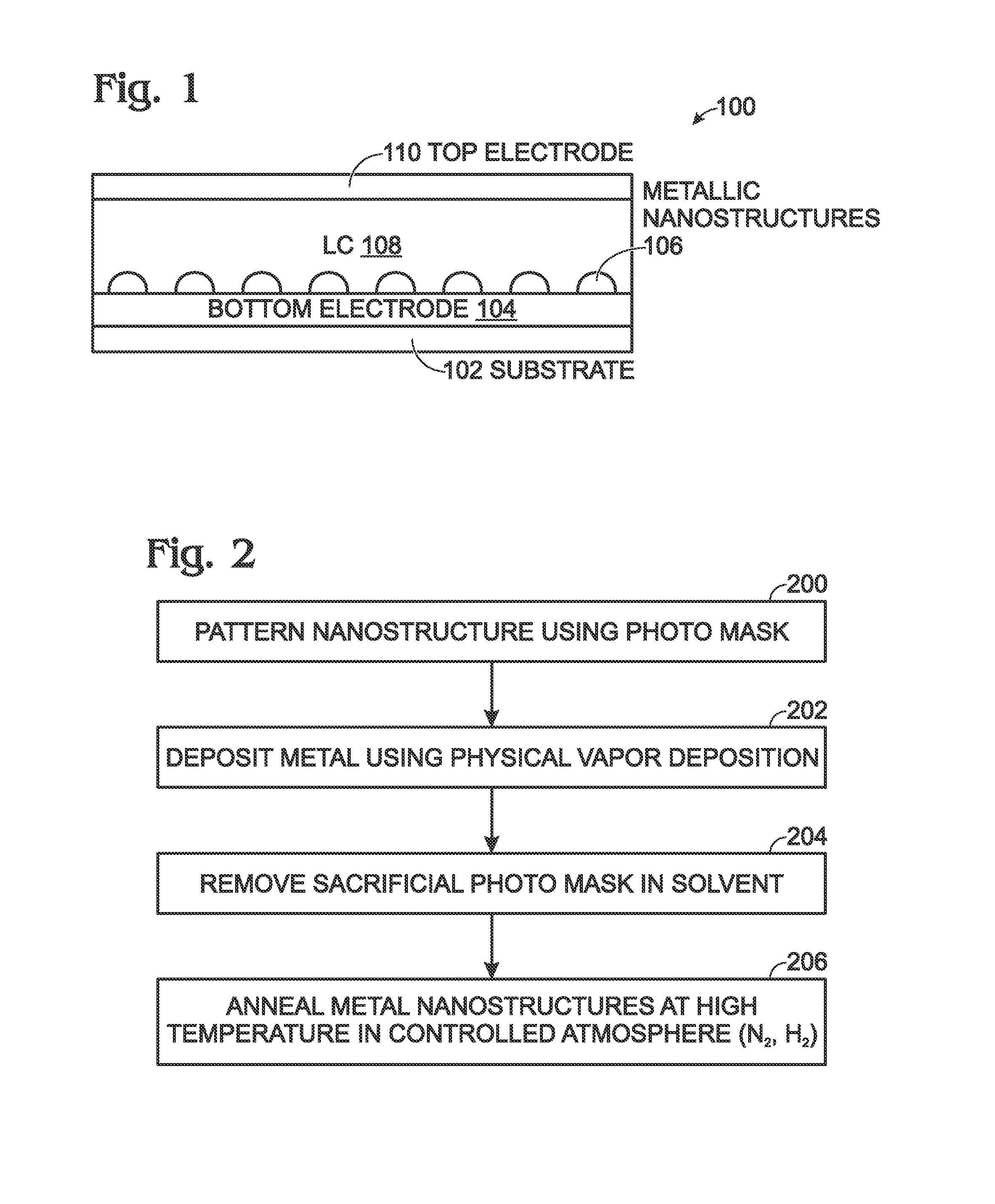
[0031]FIG. 1 is a partial cross-sectional view of a plasmonic display with stable metallic nanostructures. The display 100 comprises a glass substrate 102. A transparent bottom electrode 104, such as an indium tin oxide (ITO) material overlies the glass substrate 102. Other transparent conductive materials are well-known. In some aspects not shown, a basecoat may be interposed between the substrate and bottom electrode. Annealed metallic nanostructures 106 overlie the transparent bottom electrode 104. As explained in more detail below, the metallic nanostructures 106 generally have a dome shape. As noted in parent application Ser. No. 12 / 635,349, some of the benefits of dome-shaped nanoparticles are a larger wavelength tuning range, by maximizing the effective refractive tuning range. Further, there is little angle dependence in the reflected color due to isotropic electric field distribution.

[0032]Some exemplary metallic nanostructure materials include Ag, Au, and Al. However, othe...


PUM

PropertyMeasurementUnit
Diameteraaaaaaaaaa
Temperatureaaaaaaaaaa
Diameteraaaaaaaaaa

Abstract

A method is provided for improving metallic nanostructure stability. The method provides a substrate, and using a physical vapor deposition (PVD) process for example, deposits metallic nanostructures having a first diameter overlying the substrate. Some examples of metallic nanostructures include Ag, Au, and Al. The metallic nanostructures are annealed in an atmosphere including an inert gas and H2. The annealing temperature is less than the melting temperature the metal material in bulk form. In response to the annealing, stabilized metallic nanostructures are formed. If the stabilized metallic nanostructures are exposed to an ambient air environment the stabilized metallic nanostructure maintain the first diameter. Typically, the metallic nanostructures are initially formed having a rectangular shape with corners. After annealing, the stabilized metallic nanostructures have a dome shape.

Description

RELATED APPLICATION[0001]The application is a Continuation-in-Part of a pending application entitled, PLASMONIC ELECTRONIC SKIN, invented by Tang et al., Ser. No. 12 / 836,121, filed on Jul. 14, 2012, Attorney Docket No. SLA2752;[0002]which is a Continuation-in-Part of a pending application entitled. PLASMONIC DEVICE TUNED USING PHYSICAL MODULATION, invented by Tang et al., Ser. No. 12 / 646,585, filed on Dec. 23, 2009, Attorney Docket No. SLA2686;[0003]which is a Continuation-in-Part of a pending application entitled, PLASMONIC DEVICE TUNED USING LIQUID CRYSTAL MOLECULE DIPOLE CONTROL, invented by Tang et al., Ser. No. 12 / 635,349, filed on Dec. 10, 2009, Attorney Docket No. SLA2711;[0004]which is a Continuation-in-Part of a pending application entitled, PLASMONIC DEVICE TUNED USING ELASTIC AND REFRACTIVE MODULATION MECHANISMS, invented by Tang et al., Ser. No. 12 / 621,567, filed on Nov. 19, 2009, Attorney Docket No. SLA2685;[0005]which is a Continuation-in-Part of a pending application ...

Claims


Application Information

Patent Timeline
IPC IPC(8): B05D5/12G02F1/1343
CPCB05D5/12G02F1/13439G02F1/1334G02F1/167G02F2203/10G02F2203/34G02F2202/36G02F1/23G02F1/133514G02F2203/02
Inventor HASHIMURA, AKINORITANG, LIANGEVANS, DAVID R.
Owner SHARP KK
Why Eureka
Try Eureka