Magnetic storage apparatus, head drive controller, and head drive control method

Active Publication Date: 2013-04-04
HITACHI LTD
View PDF4 Cites 26 Cited by
  • Summary
  • Abstract
  • Description
  • Claims
  • Application Information

AI Technical Summary

Benefits of technology

[0016]The present invention reduces the probability of the elimination of information, a wrong record and others in the microwave assisted magnetic recording method more than the conventional type vertical recording method by inhibiting microwave assisted effect by the high-frequency field oscillator except in recording and further, can provide the mass reliable magnetic storage apparatus

Problems solved by technology

However, in JP-A No. 1995-244801 and JP Patent No. 4255869 and in “Bias-field-free microwave oscillator driven by perpendicularly polarized spin current” and “Microwave Assisted Magnetic Recording”, a detailed flow for applying the high-frequency generator having new structure using spin torque effect by spin transfer to an actual magnetic storage apparatus, reproducing a record using the microwave assisted recording method and appropriately using the high-frequency generator efficiently is not sufficiently researched, and the detailed flow and the problem are not disclosed, either.
The inventors have earnestly researched and tested a magnetic storage apparatus in which a high-frequency generator is built on the similar various environmental conditions to those in the conventional type; though the densification of recording can be achieved, it is clarified that there are the following large problems for practical application.
The maximum problem is that information disappears or information is rewritten even in a state in which a recording head is not operated in reproducing information and in seeking depending upon external environment although a sufficient measure fo

Method used


Image

  • Magnetic storage apparatus, head drive controller, and head drive control method
  • Magnetic storage apparatus, head drive controller, and head drive control method
  • Magnetic storage apparatus, head drive controller, and head drive control method

Examples


first embodiment

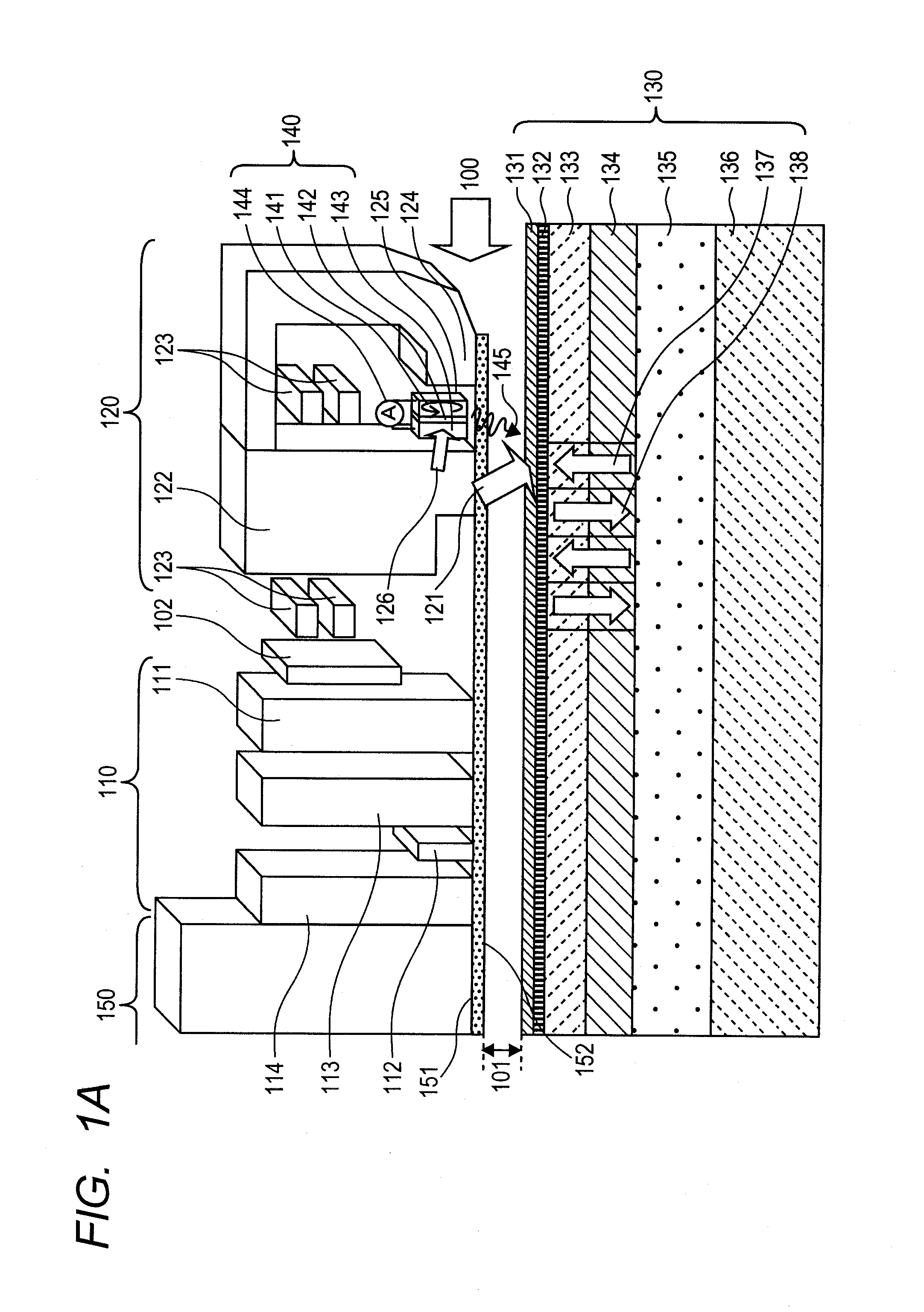
[0031]FIG. 1A is a schematic diagram showing a magnetic recording / reproducing head which is a part of a constitutional example of a magnetic storage apparatus according to the present invention. The magnetic recording / reproducing head is mainly configured by a reproducing head part 110 and a recording head part 120 respectively formed on a slider 150 run in a direction shown by an arrow 100 via clearance 101 over a magnetic recording medium 130, and a thermal flying height controller TFC 102 for controlling the clearance as described in JP Patent No. 4255869. The TFC 102 is made of high-resistivity high-thermal expansion material such as an Ni—Fe alloy and is formed of an exothermic resistor thin film of approximately 50 to 150 Ω insulated by an alumina film and others. A head protective layer 151 is made of CVD-C, filtered cathodic arc carbon (FCAC) and others and its bottom face 152 is equivalent to an air baring surface (ABS) of the magnetic recording / reproducing head. Etching wo...

second embodiment

[0077]FIG. 7 shows an especially effective embodiment in a case that recording density is higher and proof stress to an external magnetic field is more feared.

[0078]First, after the magnetic storage apparatus shown in FIG. 2 is assembled using the head drive controller, the six magnetic heads and the three magnetic recording media respectively described in the first embodiment, power input to a thermal flying height controller TFC is first adjusted (PTFC (1)) in a predetermined area of the magnetic recording medium to secure predetermined clearance between a high-frequency oscillator and the magnetic recording medium as in the first embodiment (701). Next, the high-frequency oscillator is operated at a predetermined current value ISTO (1) and a predetermined current waveform OS (1), further, recording current IW (1) is supplied to a magnetic recording pole to energize it, and a servo signal is recorded in the magnetic recording medium 130 (702). In this case, to stabilize current di...

third embodiment

[0084]For a third embodiment, an example of the highest system in cost performance will be described below.

[0085]First, the magnetic storage apparatus shown in FIG. 2 is assembled using the head drive controller described in the first embodiment, one magnetic head and one magnetic recording medium. Then, power input to a thermal flying height controller is adjusted (PTFC (1)) to secure predetermined clearance between a high-frequency oscillator 140 and the magnetic recording medium 130 in a predetermined area of the magnetic recording medium 130 as in the first embodiment (501). Next, the high-frequency oscillator 140 is operated at a predetermined current value ISTO (1), recording current IW (1) is supplied to a coil 123 of a magnetic recording pole 122 to energize it, and a servo signal is recorded in the magnetic recording medium (502). In this embodiment, an overshoot function and a reverse polarity-current supply function are not provided to a high-frequency oscillator driving ...


PUM


Abstract

A magnetic storage apparatus includes a magnetic recording medium, a microwave assisted magnetic recording head at least equipped with a magnetic recording pole that generates a recording magnetic field for writing to the magnetic recording medium and a high-frequency oscillator that generates a high-frequency field, a magnetic reproducing head that reads information from the magnetic recording medium, a signal processing unit that processes a signal written by the magnetic recording head and a signal read by the magnetic reproducing head and a unit that controls clearance between the high-frequency oscillator and the magnetic recording medium. The magnetic storage apparatus has a characteristic that the high-frequency oscillator is not operated except in recording.

Description

INCORPORATION BY REFERENCE[0001]The present application claims priority from Japanese application serial No. 2011-213976, filed on Sep. 29, 2011, the entire contents of which are hereby incorporated by reference into this application.FIELD OF THE INVENTION[0002]The present invention relates to a magnetic storage apparatus which is equipped with a magnetic recording head provided with a function for inducing a magnetic medium magnetization reversal by applying a high-frequency field to the magnetic recording medium, a head drive controller and its control method.BACKGROUND OF THE INVENTION[0003]Recently, the amount of generated information rapidly increases because of the extension of data centers and others as a result of the evolution of the Internet environment, the infiltration of cloud computing and others. It can be safely said that a magnetic storage apparatus such as a magnetic disk unit (HDD) the recording density of which is the highest and which is excellent in a bit cost ...

Claims


Application Information

Patent Timeline
IPC IPC(8): G11B21/02
CPCG11B5/3146G11B2005/0024G11B5/607
Inventor SHIROISHI, YOSHIHIROFUKUDA, HIROSHITAGAWA, IKUYAOKADA, TOMOHIRO
Owner HITACHI LTD
Why Eureka
Try Eureka