
CMC component, power generation system and method of forming a CMC component

a technology of composite components and components, applied in the direction of blade accessories, machines/engines, waterborne vessels, etc., can solve the problems of reducing the structural integrity of the cmc component, aggressive attack by the leaching compounds conventionally used to remove the silica core from investment castings,

Active Publication Date: 2013-04-04
GENERAL ELECTRIC CO
View PDF3 Cites 39 Cited by
  • Summary
  • Abstract
  • Description
  • Claims
  • Application Information

AI Technical Summary

Benefits of technology

This patent describes a ceramic matrix composite (CMC) component for a power generation system. This component includes a ceramic foam core and a CMC material surrounding at least a portion of the ceramic foam core. The ceramic foam core remains in place during operation of the component. The patent also describes a power generation system that includes a turbine blade with a ceramic foam core and a CMC material surrounding at least a portion of the ceramic foam core. The ceramic foam core remains in place during operation of the component. The patent further describes a method of forming a ceramic matrix composite component by providing a ceramic foam core, applying a reinforcing layer to the ceramic foam core, and impregnating the reinforcing layer with a matrix material. The technical effects of this patent include improved thermal performance and durability of power generation components, as well as a simplified manufacturing process.

Problems solved by technology

However, leaching compounds conventionally used to remove silica cores from investment castings aggressively attack many CMC materials, and particularly those (that contain silicon and boron, typically in the form of SiC and boron nitride (BN), respectively.
Accordingly, attempts to remove silica cores from CMC components susceptible to attack by leaching compounds suffer unacceptable attack of its internal surfaces, which reduces the structural integrity of the CMC component.

Method used


Image

  • CMC component, power generation system and method of forming a CMC component
  • CMC component, power generation system and method of forming a CMC component
  • CMC component, power generation system and method of forming a CMC component

Examples


Embodiment Construction

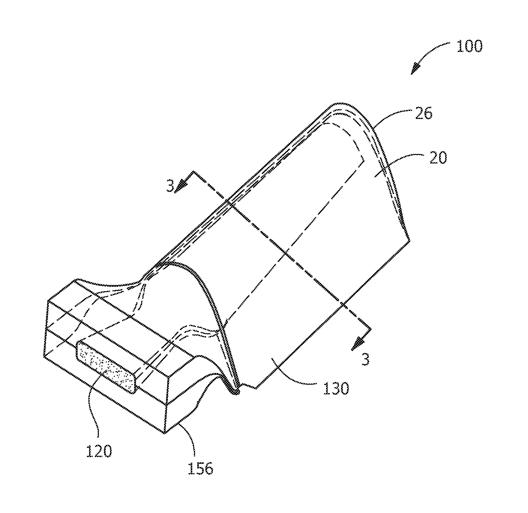
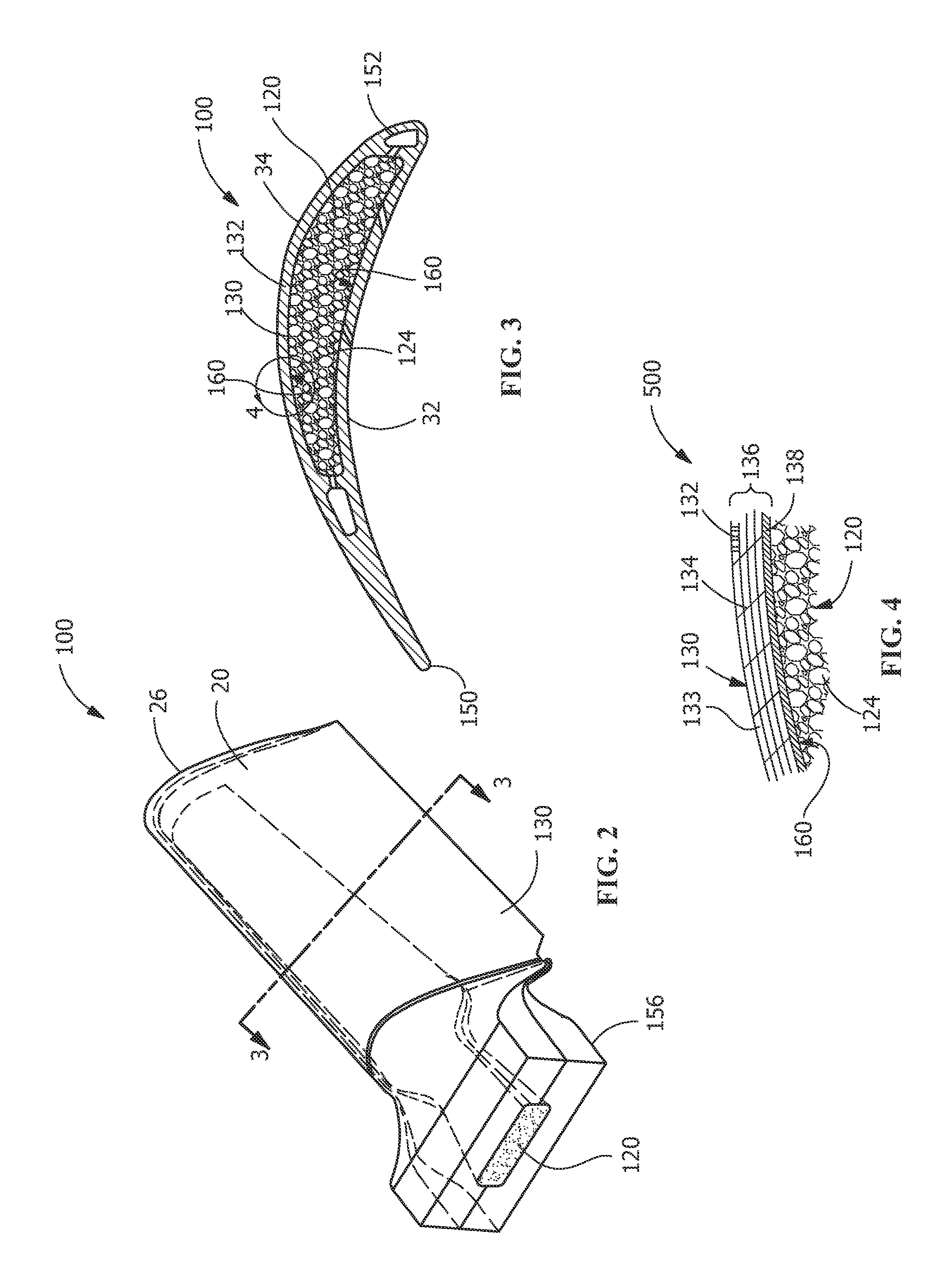
[0018]Provided is a CMC component, power generation system and method of forming a CMC component that do not suffer from the drawbacks in the prior art. CMC components, according to the present disclosure minimize or eliminate the limiting aspects of CMC material properties and manufacturing constraints and improve the mechanical loading capability. An embodiment of the disclosure is shown in FIGS. 2 and 3, but the present disclosure is not limited to the illustrated structure.

[0019]Power generation systems include, but are not limited to, gas turbines, steam turbines, and other turbine assemblies.

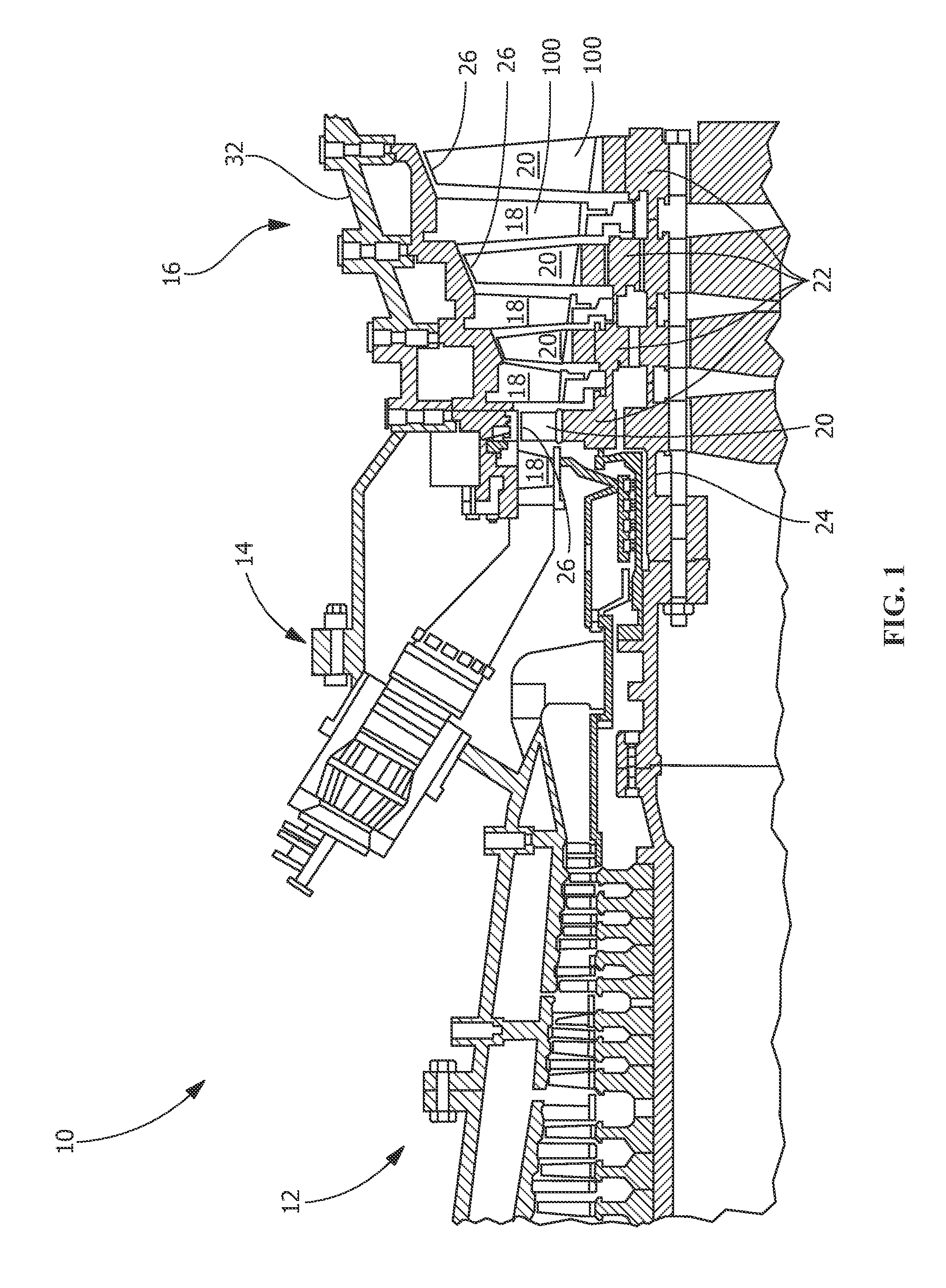
[0020]FIG. 1 shows an example of a power generation system 10, a gas turbine engine, having a compressor section 12, a combustor section 14 and a turbine section 16. In turbine section 16, there are alternating rows of stationary airfoils 18 (commonly referred to as vanes) and rotating airfoils 20 (commonly referred to as blades). Each row of blades 20 is formed by a plurality of airfoils ...


PUM


Abstract

A ceramic matrix composite component for a power generation system includes a ceramic foam core and a ceramic matrix composite material surrounding at least a portion of the ceramic foam core. The ceramic foam core remains in place during operation of the component in the power generation system. Additionally, a method of forming the ceramic matrix composite component is provided.

Description

FIELD OF THE INVENTION[0001]The present invention relates generally to power generation systems and more specifically to ceramic matrix composite components for power generation systems.BACKGROUND OF THE INVENTION[0002]Silicon carbide (SiC)-based ceramic matrix composite (CMC) materials have been proposed as materials for certain components of gas turbine engines, such as the turbine blades and vanes. Various methods are known for fabricating SiC-based CMC components, including melt infiltration (MI), chemical vapor infiltration (CVI) and polymer pyrolysis (PIP) processes. Though these fabrication techniques significantly differ from each other, each involves the use of tooling or dies to produce a near-net-shape part through a process that includes the application of heat at various processing stages. As with turbine blades and vanes formed of more conventional superalloy materials, CMC blades and vanes are primarily equipped with cavities and cooling passages for two main reasons ...

Claims


Application Information

Patent Timeline
IPC IPC(8): F01D5/14B32B5/18B32B18/00B29C44/18
CPCC04B37/001F05D2300/6033F01D5/282F01D5/284C04B2235/5248C04B2235/5268C04B2235/602C04B2235/614C04B2235/616C04B2237/04C04B2237/341C04B2237/343C04B2237/346C04B2237/36C04B2237/365C04B2237/368C04B2237/38C04B2237/61C04B2237/84C04B37/005Y10T428/249969
Inventor DIEGO, PETER DE
Owner GENERAL ELECTRIC CO
Learn More