Intelligent Backhaul Radio with Multi-Interface Switching

a backhaul radio and intelligent technology, applied in the field of data networking, can solve the problems of inability to connect all high-bandwidth data networking points with optical fiber at all times, cellular base stations, access points inevitably become very high data bandwidth, etc., and achieve the effect of avoiding or mitigating co-channel interferen

Active Publication Date: 2013-04-11
COMS IP HLDG LLC
View PDF6 Cites 61 Cited by
  • Summary
  • Abstract
  • Description
  • Claims
  • Application Information

AI Technical Summary

Benefits of technology

[0023]These IBRs overcome the limitation of obstructed LOS operation and enable many desirable capabilities such as, for example only, monitoring of spectrum activity in the vicinity of the deployment and actively avoiding or mitigating co-channel interference. To fully utilize these and other capabilities of the IBRs, it is advantageous to manage and control multiple IBRs within a geographic zone collectively as an “Intelligent Backhaul System” (or IBS).

Problems solved by technology

While deployment of optical fiber to an edge of the core data network would be advantageous from a network performance perspective, it is often impractical to connect all high bandwidth data networking points with optical fiber at all times. Instead, connections to remote edge access networks from core networks are often achieved with wireless radio, wireless infrared, and / or copper wireline technologies.
However, cellular base stations or WLAN access points inevitably become very high data bandwidth demand points that require continuous connectivity to an optical fiber core network.
These backhaul requirements cannot be practically satisfied at ranges of 300 m or more by existing copper wireline technologies.
Even if LAN technologies such as Ethernet over multiple dedicated twisted pair wiring or hybrid fiber / coax technologies such as cable modems are considered, it is impractical to backhaul at such data rates at these ranges (or at least without adding intermediate repeater equipment).
Such alignment is almost impossible to maintain over extended periods of time unless the two radios have a clear unobstructed line of sight (LOS) between them over the entire range of separation.
Furthermore, such precise alignment makes it impractical for any one such microwave backhaul radio to communicate effectively with multiple other radios simultaneously (i.e., a “point to multipoint” (PMP) configuration).
Although impressive performance results have been achieved for edge access, such results are generally inadequate for emerging backhaul requirements of data rates of 100 Mb / s or higher, ranges of 300 m or longer in obstructed LOS conditions, and latencies of 5 ms or less.
In particular, “street level” deployment of cellular base stations, WLAN access points or LAN gateways (e.g., deployment at street lamps, traffic lights, sides or rooftops of single or low-multiple story buildings) suffers from problems because there are significant obstructions for LOS in urban environments (e.g., tall buildings, or any environments where tall trees or uneven topography are present).
Because of their very narrow antenna radiation patterns and manual alignment requirements, these conventional microwave backhaul radios are completely unsuitable for applications with remote data network backhaul in obstructed LOS conditions, such as deployment on street lamps, traffic lights, low building sides or rooftops, or any fixture where trees, buildings, hills, etc., which substantially impede radio propagation from one point to another.
Additionally, such conventional microwave backhaul radios typically have little or no mechanism for avoiding unwanted interference from other radio devices at the same channel frequency, other than the narrowness of their radiation patterns.
Thus, users of such equipment are often skeptical of deployment of such conventional backhaul radios for critical applications in unlicensed spectrum bands.
This is slow, inefficient, and error prone as well as wasteful of spectrum resources due to underutilization, even with the undesirable restriction of unobstructed LOS conditions.
Furthermore, once deployed in the field, conventional microwave backhaul radios are typically islands of connectivity with little or no capability to monitor the spectrum usage broadly at the deployment location or coordinate with other radios in the vicinity to optimally use spectrum resources.
However, such a conventional EMS 216 does not dynamically modify operational policies or configurations at each CBR 132 in response to mutual interactions, changing network loads, or changes in the radio spectrum environment in the vicinity of the deployed CBRs 132.

Method used


Image

  • Intelligent Backhaul Radio with Multi-Interface Switching
  • Intelligent Backhaul Radio with Multi-Interface Switching
  • Intelligent Backhaul Radio with Multi-Interface Switching

Examples


Embodiment Construction

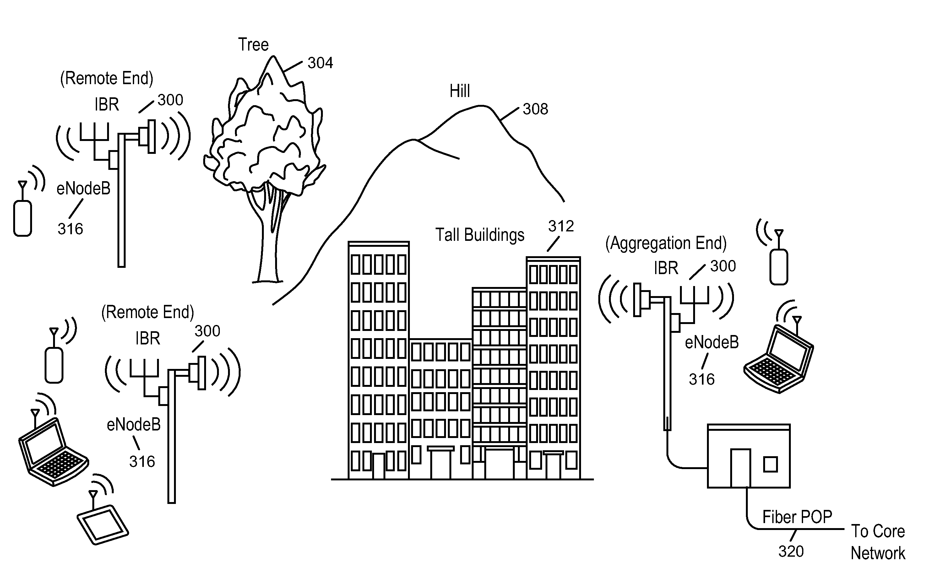
[0050]FIG. 3 illustrates deployment of intelligent backhaul radios (IBRs) in accordance with an embodiment of the invention. As shown in FIG. 3, the IBRs 300 are deployable at street level with obstructions such as trees 304, hills 308, buildings 312, etc. between them. The IBRs 300 are also deployable in configurations that include point to multipoint (PMP), as shown in FIG. 3, as well as point to point (PTP). In other words, each IBR 300 may communicate with one or more than one other IBR 300.

[0051]For 3G and especially for 4th Generation (4G), cellular network infrastructure is more commonly deployed using “microcells” or “picocells.” In this cellular network infrastructure, compact base stations (eNodeBs) 316 are situated outdoors at street level. When such eNodeBs 316 are unable to connect locally to optical fiber or a copper wireline of sufficient data bandwidth, then a wireless connection to a fiber “point of presence” (POP) requires obstructed LOS capabilities, as described ...


PUM


Abstract

A intelligent backhaul system is disclosed to manage and control multiple intelligent backhaul radios within a geographic zone. The intelligent backhaul system includes multiple intelligent backhaul radios (IBRs) that are able to function in both obstructed and unobstructed line of sight propagation conditions, one or more intelligent backhaul controllers (IBCs) connecting the IBRs with other network elements, and an intelligent backhaul management system (IBMS). The IBMS may include a private and / or public server and / or agents in one or more IBRs or IBCs.

Description

CROSS-REFERENCE TO RELATED APPLICATIONS[0001]The present application is a continuation application of U.S. patent application Ser. No. 13 / 415,778, filed on Mar. 8, 2012, which is a continuation application of U.S. patent application Ser. No. 13 / 271,051, filed on Oct. 11, 2011, and the disclosures of which are hereby incorporated by reference in their entirety.BACKGROUND[0002]1. Field[0003]The present disclosure relates generally to data networking and in particular to a backhaul system to manage and control multiple backhaul radios that connect remote edge access networks to core networks in a geographic zone.[0004]2. Related Art[0005]Data networking traffic has grown at approximately 100% per year for over 20 years and continues to grow at this pace. Only transport over optical fiber has shown the ability to keep pace with this ever-increasing data networking demand for core data networks. While deployment of optical fiber to an edge of the core data network would be advantageous f...

Claims


Application Information

Patent Timeline
Patent Type & Authority Applications(United States)
IPC IPC(8): H04W72/04H04W84/12H04W28/26H04L45/02
CPCH04B7/0691H04W74/04H04B7/0874H04W92/20H04W72/21H04W72/12H04W72/54G06F8/65H04B7/0469H04L5/14H04L5/1469H04L41/0803H04L45/02H04L67/34H04W48/16H04W72/044H04W88/14
Inventor NEGUS, KEVIN J.DUFFY, KEVIN J.
Owner COMS IP HLDG LLC
Why Eureka
Try Eureka