Method and device for operating an internal combustion engine in the event of a fault in a crankshaft sensor

a crankshaft sensor and internal combustion engine technology, applied in the direction of non-mechanical valves, electrical control, valve drives, etc., can solve the problems of deteriorating the camshaft is no longer available, etc., to improve the exhaust gas performance of the internal combustion engine, improve the internal combustion engine's exhaust gas performance, and reduce the control effort required

Inactive Publication Date: 2013-04-18
ROBERT BOSCH GMBH
View PDF9 Cites 11 Cited by
  • Summary
  • Abstract
  • Description
  • Claims
  • Application Information

AI Technical Summary

Benefits of technology

[0013]In another specific embodiment, the adjustment of the second camshaft occurs between two permanently defined angles of rotation within an adjustment range of the second camshaft. This reduces the control effort required for the phase adjuster. The adjustment range typically amounts to 60° of the crankshaft.
[0014]Alternatively, the adjustment of the second camshaft occurs steplessly within the adjustment range of the camshaft. Although it requires an elaborate control process, the stepless adjustment of the camshaft makes it possible to react comfortably to various operating states of the internal combustion engine and thus to adjust the exhaust gas performance of the internal combustion engine advantageously.
[0015]A further development of the present invention relates to a device for operating an internal combustion engine in the event of a fault in a crankshaft sensor, the internal combustion engine having at least two adjustable camshafts and a rotational speed and / or the position of the internal combustion engine being ascertained from a signal taken from the camshaft rotation. In order to improve the exhaust gas performance of the internal combustion engine even in a crankshaft emergency operating mode, only a first camshaft is used to determine the speed of the internal combustion engine, while means are provided for adjusting the second camshaft in its angle of rotation in order to set a variable valve operating mechanism on the intake or exhaust valves of the internal combustion engine that are driven by the second camshaft. This system brings about an improvement of the exhaust gas performance of the internal combustion engine even in the crankshaft emergency operating mode.
[0016]In one development, the first and the second camshaft are controlled in their respective rotary motion by a control unit, the control unit, which sets the first camshaft in a reference position with respect to the crankshaft, is connected to a camshaft sensor that detects the rotary motion of the first camshaft, from which the control unit determines the speed and / or the position of the internal combustion engine and as a function of the ascertained speed or position of the internal combustion engine controls an adjusting device connected to the second camshaft for turning the angle of rotation of the second camshaft out of its original position. In addition to determining precisely the position and / or speed of the internal combustion engine using only one camshaft, variable valve opening times are set using the second camshaft even in a crankshaft emergency operating mode. Turning the second camshaft out of its original position improves the exhaust gas performance of the internal combustion engine by optimizing the ratio of fresh air and fuel, the positive influence on the exhaust gas performance remaining in effect even in the crankshaft emergency operating mode. A suitable actuating mechanism is used as an actuator, which operates electrically or hydraulically and performs this adjustment simply in a mechanical manner, and which for transmitting force is situated at the end of each camshaft.

Problems solved by technology

The camshafts are thus no longer available for a camshaft adjustment in the various operating ranges of the internal combustion engine, which results in a deterioration of the exhaust gas performance of the internal combustion engine.

Method used


Image

  • Method and device for operating an internal combustion engine in the event of a fault in a crankshaft sensor
  • Method and device for operating an internal combustion engine in the event of a fault in a crankshaft sensor
  • Method and device for operating an internal combustion engine in the event of a fault in a crankshaft sensor

Examples


Embodiment Construction

[0020]Identical features are indicated by the same reference symbols.

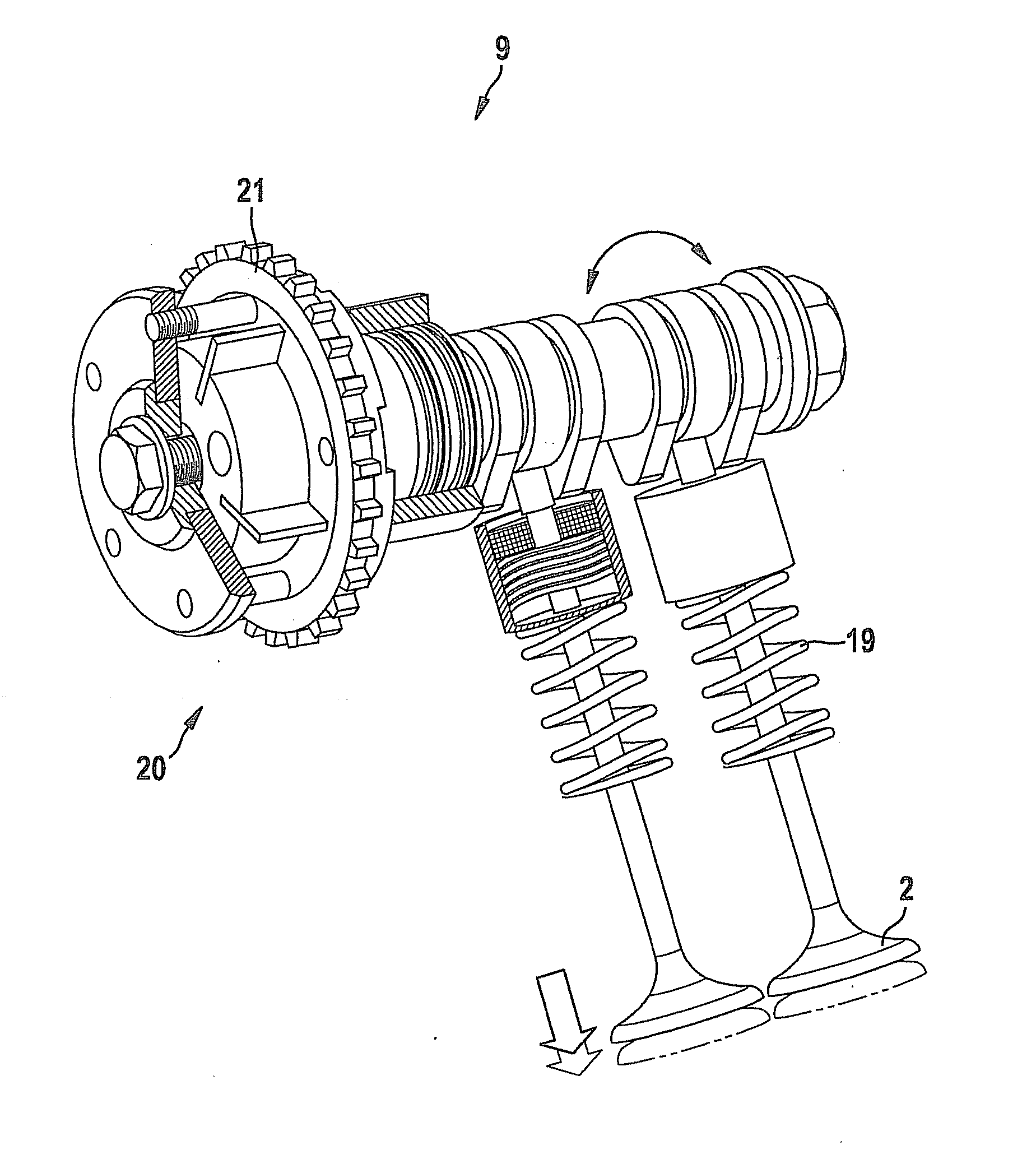
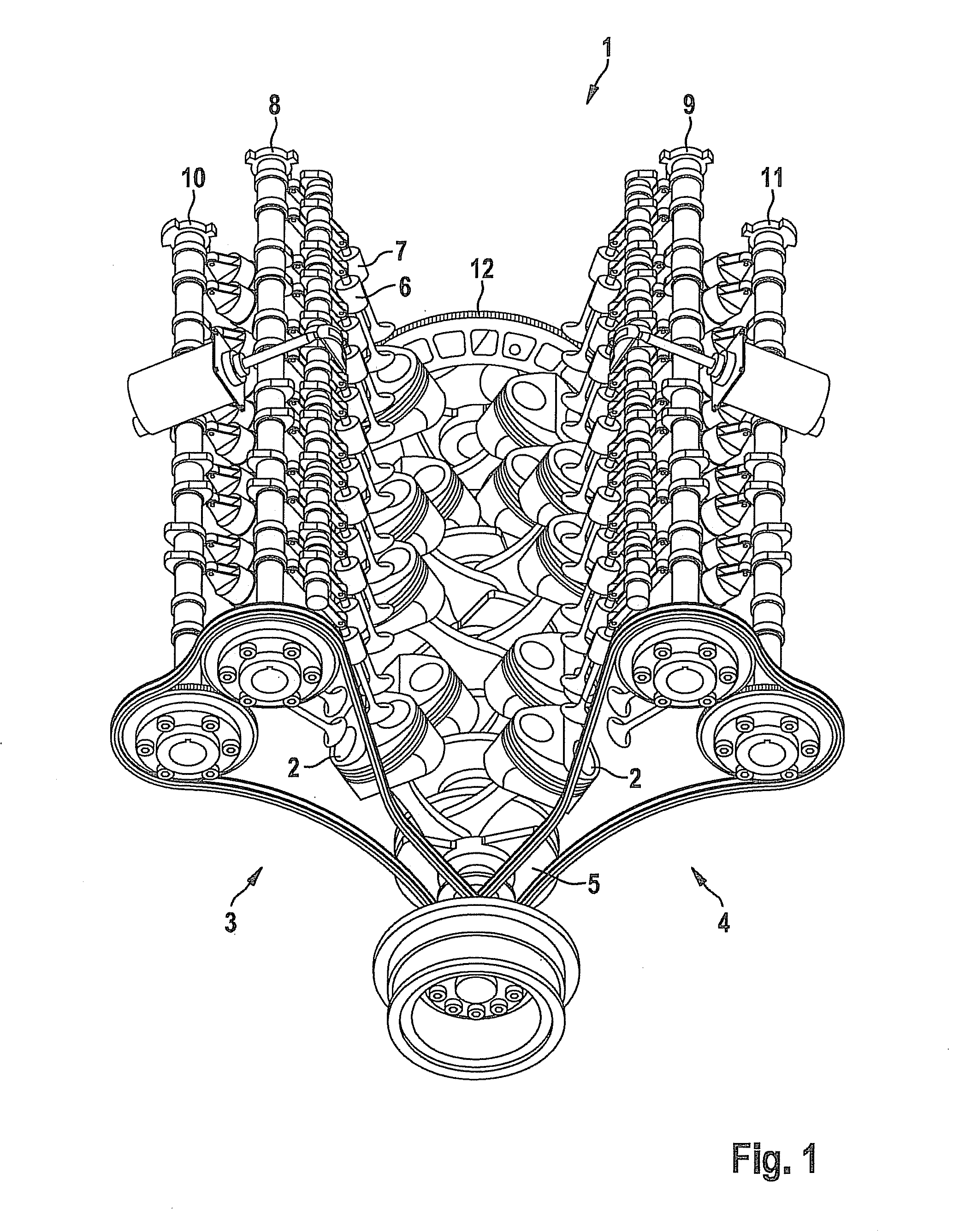
[0021]FIG. 1 shows a basic representation of an internal combustion engine 1 in the shape of a V. In this instance, cylinders 2 of internal combustion engine 1 are arranged in a v-shape on two planes 3, 4, a crankshaft 5 being situated at the intersection of the two planes 3, 4. Each plane 3, 4 is typically called a bank. Each cylinder 2 is equipped with one or more intake valves 6 and one exhaust valve 7. Fresh air and fuel are conveyed through intake valve 6 into the respective cylinder 2 of internal combustion engine 1, while the combustion products of cylinder 2 in the form of exhaust gas are discharged from internal combustion engine 1 via exhaust valve 7. Intake valves 6 of first plane 3 of cylinders 2 are connected to a first camshaft 8, while exhaust valves 7 of first plane 3 are operated by a second camshaft 10. Analogously, intake valves of second plane 4 of cylinders 2 connect to a third camshaft 9, and ...


PUM


Abstract

A method for operating an internal combustion engine in the event of a fault in a crankshaft sensor is provided, the internal combustion engine having at least two camshafts and a speed and/or a position of the internal combustion engine being derived from a signal taken from the camshaft. In order to improve the exhaust gas performance of the internal combustion engine even in a crankshaft emergency operating mode, only a first camshaft is used to determine the speed and/or the position of the internal combustion engine, while the second camshaft. is adjusted in its angle of rotation in order to set a variable valve operating mechanism on the intake and exhaust valves of the internal combustion engine that are driven by the second camshaft.

Description

BACKGROUND OF THE INVENTION[0001]1. Field of the Invention[0002]The present invention relates to a method for operating an internal combustion engine in the event of a fault in a crankshaft sensor, the internal combustion engine having at least two camshafts and a rotational speed and / or a position of the internal combustion engine being derived from a signal taken from the camshaft, and to a device for implementing the method.[0003]2. Description of the Related Art[0004]In today's motor vehicles it is important to determine the speed of the internal combustion engine precisely since this parameter enters into numerous open-loop and closed-loop control processes of the motor vehicle. Usually, this speed is derived from the rotational speed of a crankshaft, which is driven by the mechanical energy generated in the combustion process. For this purpose, the crankshaft is scanned by a crankshaft sensor, which detects the speed and position of the crankshaft. The signal is provided by a ...

Claims


Application Information

Patent Timeline
Patent Type & Authority Applications(United States)
IPC IPC(8): F01L1/344
CPCF01L1/34F01L2001/0537F01L2001/34496F01L1/344F01L2800/12F01L2820/041F01L2820/042F01L2800/11F01L1/04F01L13/00F02D13/00F02D41/22F02D45/00F01L9/20
Inventor PIETSCH, ELMARNEFZER, ULRICH-MICHAELDERINGER, CARSTEN
Owner ROBERT BOSCH GMBH
Why Eureka
Try Eureka