Optical motion tracking of an object

an optical motion and object technology, applied in the field of optical motion tracking of objects, can solve the problems of single camera solutions however by nature limited in resolution, and achieve the effect of improving the known object tracking system and limited in resolution

Inactive Publication Date: 2013-04-18
RIGSHOSPITALET
View PDF5 Cites 93 Cited by
  • Summary
  • Abstract
  • Description
  • Claims
  • Application Information

AI Technical Summary

Benefits of technology

[0009]These single camera solutions are however by nature limited in resolution because due to the powerful electromagnetic field in the scanner bore the camera must be located outside the scanner...

Problems solved by technology

These single camera solutions are however by nature limited in resolution because due to the powerful electromagnetic field in the scanner bore the ca...

Method used


Image

  • Optical motion tracking of an object
  • Optical motion tracking of an object
  • Optical motion tracking of an object

Examples


Embodiment Construction

[0041]Marker Plate

[0042]One aspect of the invention relates to the marker plate itself, i.e. a marker plate for use in an optical motion tracking application comprising a pattern on at least one side of the plate.

[0043]In one embodiment the pattern comprises three primary markers, the positions of the three primary markers forming a triangle, such as an equilateral triangle or an isosceles triangle. Distribution of the three primary markers in a triangular shape may facilitate determination of 3D motion of the marker plate. If for example the primary markers are distributed in a straight line the centre of mass of the three markers does not change during a rotation around that line, whereby this particular 3D motion in undetectable.

[0044]In one embodiment of the invention the pattern comprises one or more disk shaped markers, such as two or three disk shaped markers. Further, at least one marker may be an annulus. The pattern may thus comprise one, two or three markers, such as disk...


PUM


Abstract

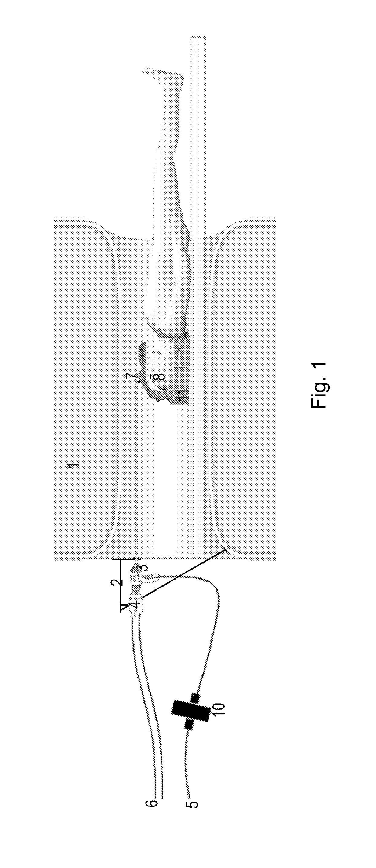
The present invention relates to a system and a method for monitoring/tracking the movement of an object in a location which is difficult to access, such as the movement of a patient in a clinical MRI scanner. This is achieved by an optical motion tracking system for determining the movement of an object at least partly located in a volume of difficult access and/or at least partly located in an electromagnetic field, said system comprising a borescope for imaging a pattern on the object or a surface part of the object with a camera, said pattern or surface part located adjacent to a distal end of the borescope and said camera attached to a proximal end of said borescope, and image processing means for calculating the movement of said pattern or surface part relative to the distal end of the borescope based on a plurality of frames/images captured by the camera. The invention further relates to the use of a borescope for motion tracking of an object and a marker plate suitable for use in the motion tracking system.

Description

[0001]The present invention relates to a system and a method for monitoring / tracking the movement of an object in a location which is difficult to access, such as the movement of a patient in a clinical MRI scanner. The invention further relates to the use of a borescope for motion tracking of an object and a marker plate suitable for use in a motion tracking system.BACKGROUND OF INVENTION[0002]Modern clinical / medical in vivo scanning techniques, such as Magnetic Resonance Imaging (MRI), are excellent for assessing the structure, physiology, chemistry and function of human organs, in particular the brain. Because the object of interest, i.e. the patient, is often imaged in many slices and scanning steps in order to build a complete three dimensional view, scans are of long duration, usually lasting several minutes. To increase resolution (detail) of a scan, more slices and more scanning steps must be used, which further increases the duration of a scan. Many clinical imaging techniq...

Claims


Application Information

Patent Timeline
IPC IPC(8): G01C11/04
CPCA61B5/055A61B5/1127G01C11/04G01R33/34046G02B23/2476G01R33/283G01B11/26G01B11/002
Inventor OHLHUES, ANDERSTHOMSEN, CARSTEN
Owner RIGSHOSPITALET
Why Eureka
Try Eureka