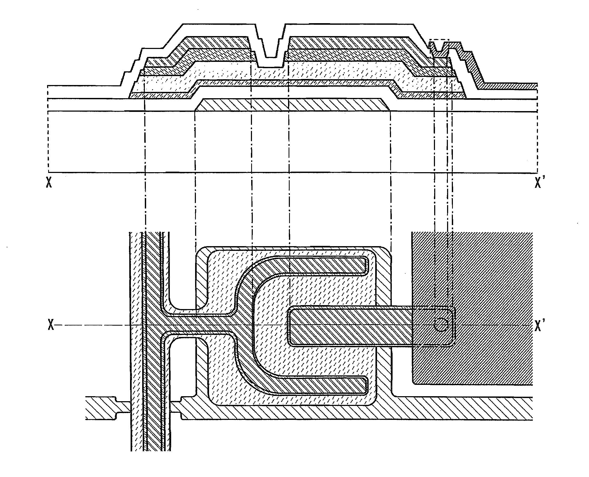
Methods for manufacturing thin film transistor and display device
a thin film transistor and display device technology, applied in semiconductor/solid-state device manufacturing, semiconductor devices, electrical equipment, etc., can solve the problems of low current-driving capability, low mobility of thin film transistors using amorphous semiconductor films, and inability to achieve narrower frame parts, so as to improve the image quality of display devices
- Summary
- Abstract
- Description
- Claims
- Application Information
AI Technical Summary
Benefits of technology
Problems solved by technology
Method used
Image
Examples
embodiment mode 1
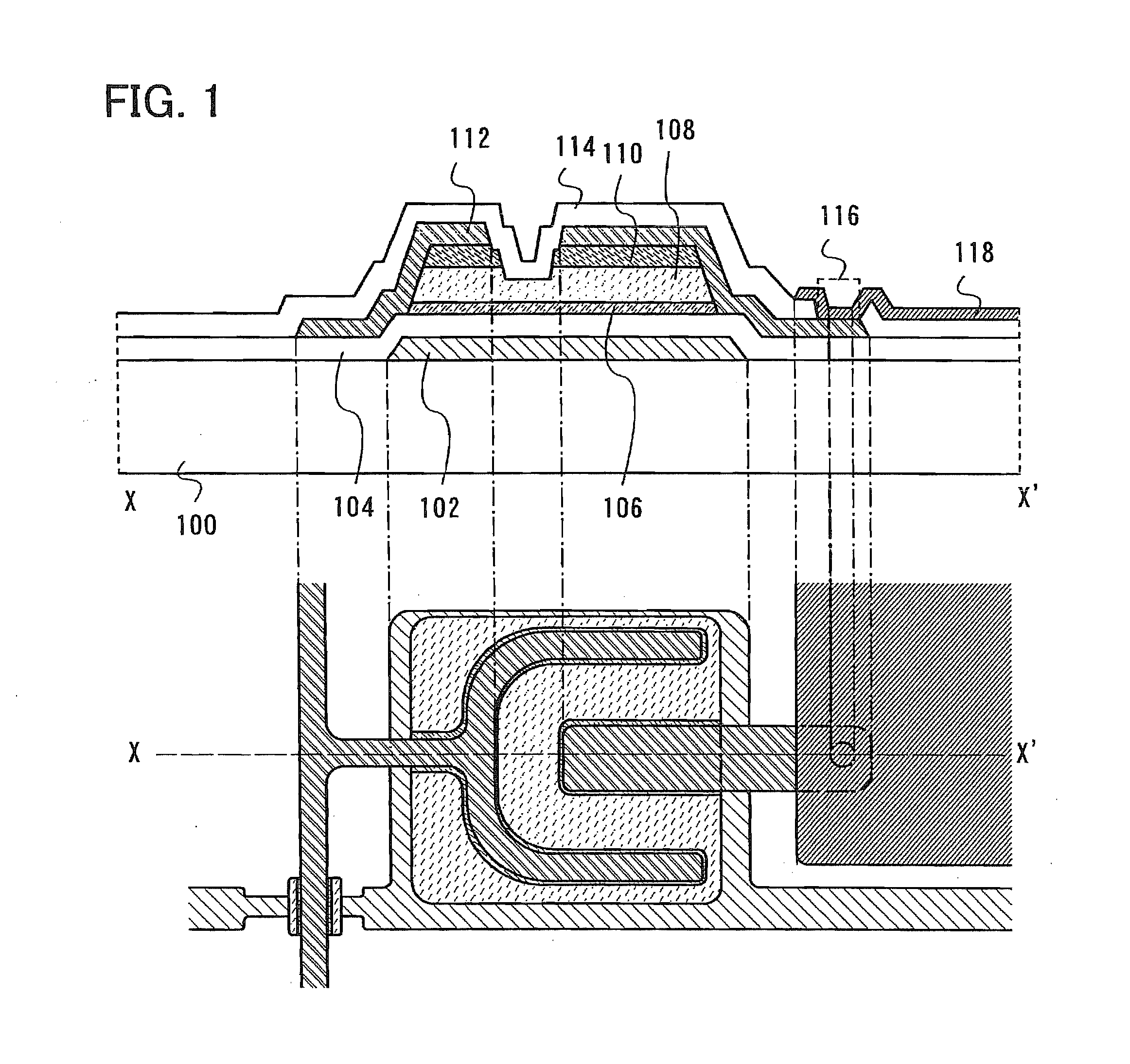
[0083]In Embodiment Mode 1, a method for manufacturing a thin film transistor according to the present invention and the thin film transistor manufactured by the method will now be described with reference to drawings.
[0084]FIG. 1 is a top view and a cross-sectional view of a thin film transistor according to the present invention as an example. The thin film transistor illustrated in FIG. 1 includes a gate electrode layer 102 over a substrate 100, a gate insulating layer 104 over the gate electrode layer 102, a semiconductor layer 106 over the gate insulating layer 104, a buffer layer 108 over the semiconductor layer 106, source and drain regions 110 over a part of the buffer layer 108, source and drain electrode layers 112 over the source and drain regions 110, and an insulating layer 114 over the source and drain electrode layers 112. Each of the layers is patterned into a desired shape. The insulating layer 114 serves as a protective layer.
[0085]In addition, specifically, the se...
embodiment mode 2
[0195]In Embodiment Mode 2, a method for manufacturing a thin film transistor of the present invention, which is different from that of Embodiment Mode 1, is described with reference to drawings. Specifically, no resist mask is used in forming a back channel, and a back channel is formed using source and drain electrode layers as a mask.
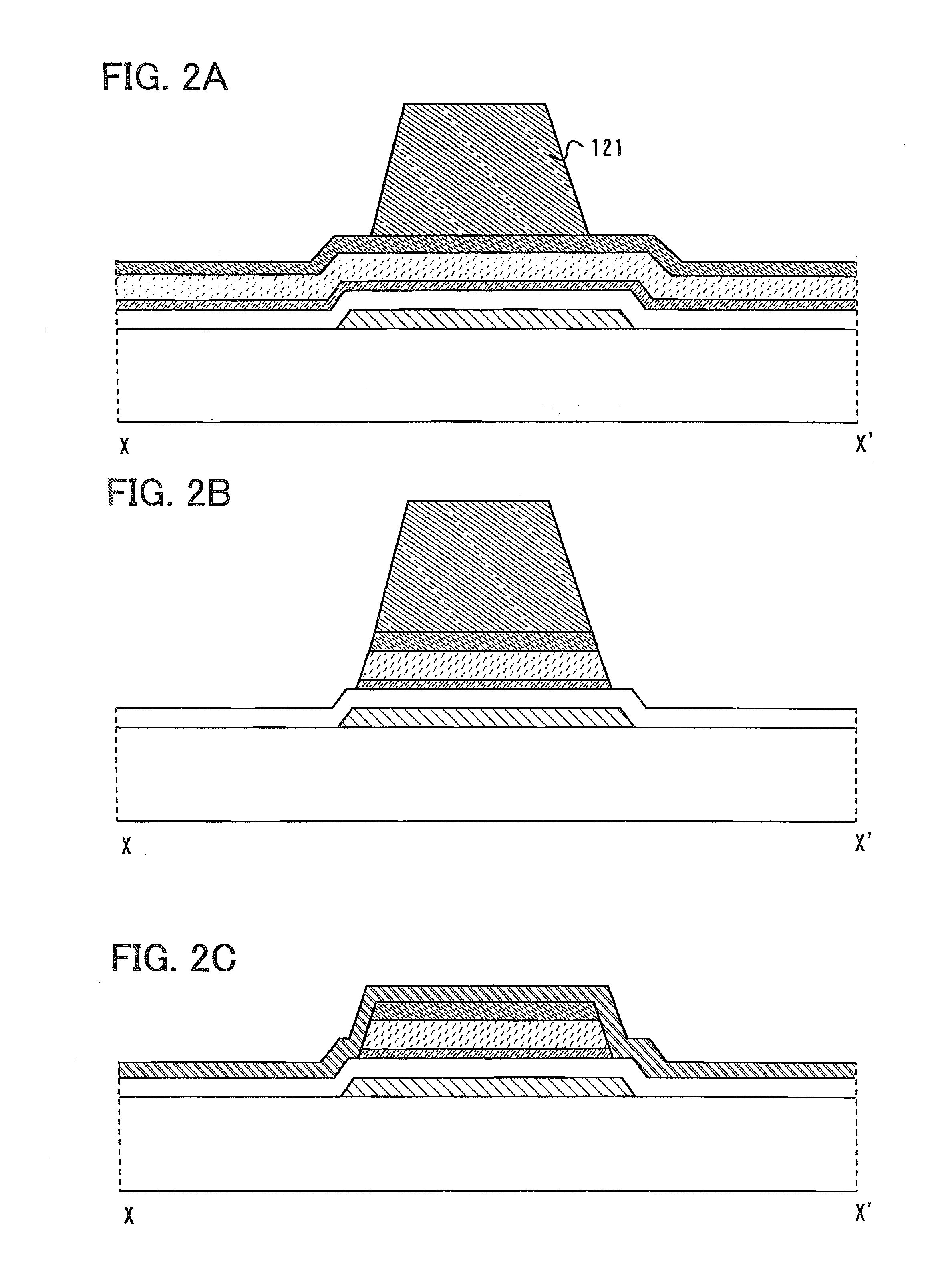
[0196]One mode of the method for manufacturing a thin film transistor of the present invention is described with reference to FIGS. 7A to 7C and FIGS. 8A and 8B.
[0197]First, steps up to and including the etching of a conductive layer serving as source and drain electrodes are conducted (FIG. 7A). FIG. 7A is similar to FIG. 3A. By this step, the source and drain electrodes are formed. In etching the conductive layer, a resist mask 126 is used.
[0198]After that, the resist mask 126 is removed (FIG. 7B). Then, an impurity semiconductor layer and a buffer layer are partially etched using the source and drain electrodes as a mask to separate a source regio...
embodiment mode 3
[0219]In Embodiment Mode 3, a method for manufacturing a thin film transistor of the present invention, which is different from those of Embodiment Modes 1 and 2, is described with reference to drawings. Specifically, a multi-tone mask is used.
[0220]First, a stacked body in which layers up to and including a conductive layer have been formed in a manner similar to the manufacturing method of Embodiment Mode 1 is obtained. Then, a resist mask 136 having a depression portion (concave portion) at a desired position is formed over the stacked body (FIG. 11A). The resist mask can be a multi-tone mask. As examples of the multi-tone mask, a grey tone mask or a halftone mask can be given, and a known multi-tone mask may be used.
[0221]Then, a microcrystalline semiconductor layer, an amorphous semiconductor layer and an impurity semiconductor layer are etched using the resist mask 136. By this etching, the semiconductor layer, the buffer layer and the impurity semiconductor layer are separate...
PUM
 Abstract
Description
Claims
Application Information
 - R&D
- Intellectual Property
- Life Sciences
- Materials
- Tech Scout
- Unparalleled Data Quality
- Higher Quality Content
- 60% Fewer Hallucinations
Browse by: Latest US Patents, China's latest patents, Technical Efficacy Thesaurus, Application Domain, Technology Topic, Popular Technical Reports.
© 2025 PatSnap. All rights reserved.Legal|Privacy policy|Modern Slavery Act Transparency Statement|Sitemap|About US| Contact US: help@patsnap.com


