System and method for controlling a remote medical device guidance system in three-dimensions using gestures

a technology of three-dimensional guidance and medical device, applied in the field of user interfaces and devices therefore for robotic control of electrophysiology lab diagnostic and therapeutic equipment, can solve the problems of delayed implementation of requests for event markers, segment recordings, lesion markers,

Active Publication Date: 2013-04-18
ST JUDE MEDICAL ATRIAL FIBRILLATION DIV
View PDF6 Cites 102 Cited by
  • Summary
  • Abstract
  • Description
  • Claims
  • Application Information

AI Technical Summary

Benefits of technology

[0011]One advantage of the methods and apparatuses described, depicted and claimed herein is that they provide an EP physician or other user with the capability of directly controlling a robotic catheter system. In an embodiment, a system for enabling a user to remotely control a robotic catheter system includes a motion capture apparatus and an electronic control unit. The motion capture apparatus is configured to capture motion of a user in a sensing volume and generate output data indicative of the captured user motion. The electronic control unit includes one or more processors and memory. The system further includes gesture recognition logic stored in the memory and configured to execute on the one or more processors. The gesture recognition logic is configured to recognize a user gesture based on the output data generated by the motion capture apparatus. The system further includes interpreter logic stored in the memory and configured to be executed by the one or more processors. The interpreter logic is configured to translate the recognized user gestures to a corresponding robotic catheter control command wherein the command is configured to control an aspect of the operation of the robotic catheter system. The electronic control unit is configured to communicate the command to the robotic catheter system.

Problems solved by technology

The physician's sterile gloved hands are typically engaged with the catheter handle and shaft next to the patient and he or she is therefore unable to directly make changes himself to any of the EP systems.
While some commands are straightforward, for example, “LAO View”, “record that” and “stop pacing”, other commands are not as easy to clearly communicate.
Furthermore, implementation of requests for event markers, segment recordings, lesion markers and the like can be delayed by the time it takes the technician to hear, understand and act on a physician's command.
Ambient discussions and / or equipment noise in and around the EP lab can increase this delay.

Method used


Image

  • System and method for controlling a remote medical device guidance system in three-dimensions using gestures
  • System and method for controlling a remote medical device guidance system in three-dimensions using gestures
  • System and method for controlling a remote medical device guidance system in three-dimensions using gestures

Examples


first embodiment

[0056]FIG. 3A is a plan view of a bedside interface device comprising a computer 26a, suitable for use in the EP lab of FIG. 2, and showing a first application-specific user interface. The computer 26a includes a touch-responsive display panel and thus may be referred to hereinafter sometimes as a touch panel computer. The touch panel computer 26a, as shown in inset in FIG. 3A, includes an electronic control unit (ECU) having a processor 60 and a computer-readable memory 62, user interface (UI) logic 64 stored in the memory 62 and configured to be executed by processor 60, a microphone 66 and voice recognition logic 68. In an embodiment, voice recognition logic 68 is also stored in memory 62 and is configured to be executed by processor 60. In an embodiment, the touch panel computer 26a is configured for wireless communication to base interface 28 (best shown in FIG. 2). In addition, the touch panel computer 26a is configured to draw operating power at least from a battery-based pow...

second embodiment

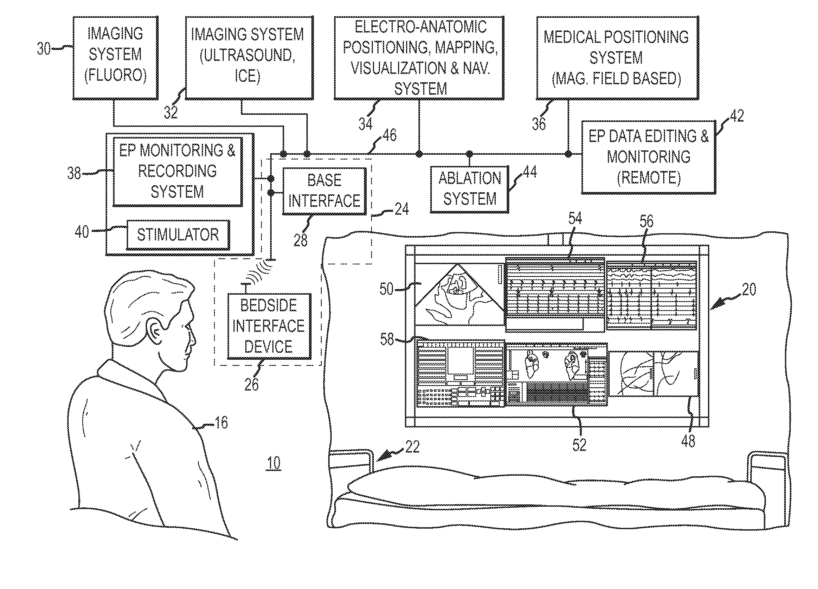
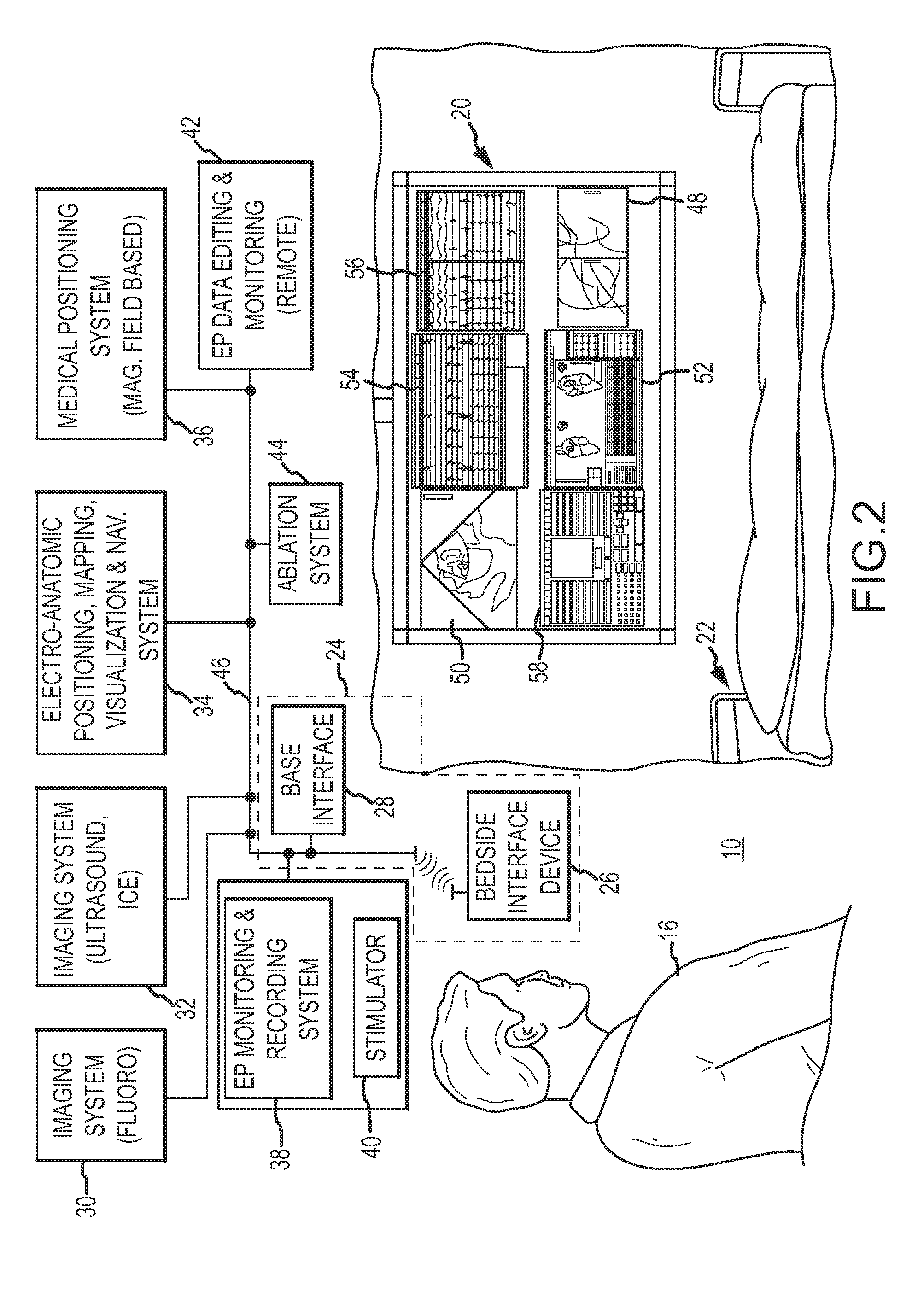
[0077]FIG. 7A is a diagrammatic and block diagram view of the bedside interface device, comprising an electronic wand system 26b. As with touch panel computer 26a, wand system 26b is configured to allow the EP physician to take control, bedside of the patient, of an EP diagnostic or therapeutic system, such as the electro-anatomic mapping system 34. The wand system 26b includes a wireless remote control portion 102, an optical emitter portion 104, and a base interface 28b, which may be coupled to the desired, target EP system through either a wired or wireless connection. The wand system 26b incorporates remote control technology, and includes the ability to detect and interpret motion of the remote control indicative of an EP physician's command or other instruction, detect and interpret key-presses on the remote control, and / or detect and interpret motion / keypress combinations.

[0078]Since the wand system 26b is contemplated as being used in the sterile procedure room, multiple emb...

fourth embodiment

[0082]FIG. 8 is a diagrammatic and block diagram view of the bedside interface device, comprising a motion capture apparatus 26d. As with touch panel computer 26a, wand system 26b and integrated system 26c, motion capture apparatus 26d is configured to allow the EP physician to take control, bedside of the patient, of an EP diagnostic or therapeutic system, such as electro-anatomical mapping system 34. The motion capture apparatus 26d includes a capture apparatus 116 having both an optical sub-system 118 and a microphone sub-system 120 where the apparatus 116 is coupled to a base interface 28b. The apparatus 116 is configured to optically detect the motion or physical gestures of the EP physician or other user when such movements occur within a sensing volume 122. The base interface 28b may be coupled to the desired, target EP system through either a wired or wireless connection.

[0083]The motion capture apparatus 26d includes the capability to detect hand / arm / leg / trunk / facial motion...


PUM


Abstract

A system for enabling a user to remotely control a robotic medical device system includes a motion capture apparatus to capture motion of a user in a sensing volume and generate indicative output data. The system includes a control unit configured to execute gesture recognition logic that recognizes a user gesture based on analysis of the indicative output data. The control unit executes interpreter logic that is configured to translate the recognized user gesture into a corresponding robotic medical device control command configured to control an aspect of the operation of the robotic medical device system.

Description

CROSS-REFERENCES TO RELATED APPLICATIONS[0001]This application is a continuation-in-part of U.S. application Ser. No. 13 / 208,924, filed 12 Aug. 2011, now pending (the '924 application). This application is also a continuation-in-part of U.S. application Ser. No. 12 / 507,175, filed 22 Jul. 2009, now allowed (the '175 application). This application is also a continuation-in-part of U.S. application Ser. No. 13 / 637,401, filed 26 Sep. 2012, now pending (the '401 application), which is the national stage of international application no. PCT / US11 / 30764, with an international filing date of 31 Mar. 2011 (the '764 application), which claims priority to U.S. provisional application No. 61 / 319,795, filed 31 Mar. 2010 (the '795 application). The '924 application, the '175 application, the '401 application, the '764 application, and the '795 application are all hereby incorporated by reference as though fully set forth herein.BACKGROUND[0002]a. Technical Field[0003]The instant disclosure relates...

Claims


Application Information

Patent Timeline
Patent Type & Authority Applications(United States)
IPC IPC(8): A61B19/00
CPCG06T19/003G06T2210/41G06F3/017A61B5/042A61B19/56A61B34/25A61B5/283G06V40/20A61B2034/258A61B34/30A61B34/74A61B2034/741A61B34/76B25J9/161G06F3/014G06F3/03545
Inventor OLSON, ERIC S.
Owner ST JUDE MEDICAL ATRIAL FIBRILLATION DIV
Why Eureka
Try Eureka